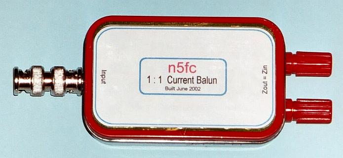
N5ESE's 1:1 Current Balun
(click on any picture to see larger version)
(click on any picture to see larger version)
| NOTE: 'N5FC' is my former call. This project was constructed while that call was valid, and you may observe references to it. |
Here's another handy little Altoids QRP project. For Field Day 2002, I wanted to use my new Elecraft K1 (which has an automatic antenna tuner built-in) to feed a full-wave loop on 40 meters, to use on all bands 40 - 15. To preserve the feedline balance (I used 300-ohm ladder line), I needed a balun at the output of the K1's antenna tuner. This 1:1 balun did the trick quite nicely.
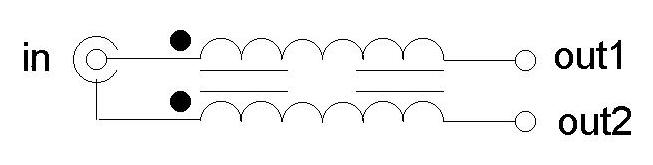
The classic 1:1 current balun's circuit looks like so:
Two versions were built. The first was wound with 16 turns of side-by-side AWG 20 teflon-coated wire onto a FT114-43 core. It is shown below:

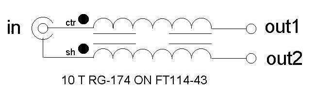
It did a marvelous job on Field day, but subsequent measurements using my MFJ Antenna Analyzer showed that the SWR rose gradually from 1.1:1 at 21 MHz to 1.8:1 at 30 MHz (into a 50-ohm dummy load). I felt I could do better, using small-diameter coax instead of parallel pairs, and this proved to be true, yielding 1.05:1 at 21 MHz and only 1.15:1 at 30 MHz. Below are the schematic and picture of the coax-wound version, using 10 turns of RG-174 mini-coax:
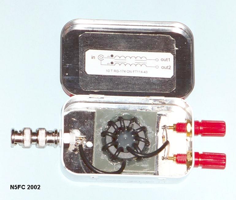
Construction-wise, on both versions, an isolated BNC is used at the input (Amphenol 31-010), though a garden variety BNC connector (non-isolated) mounted directly to the Altoids box could as easily been used. I grabbed a piece of 3/32" thick PC board that I had laying around as scrap, peeled off the copper, and used that as the "mounting plate", mounting the completed toroid with hot glue. This gave the coil a little clearance from the Altoids case's metal, hopefully minimizing distributed capacitance. Then, standard banana plug binding posts were used for connecting the feedline to the balumn's output. Though not shown in the schematic, two 100K resistors are added , one on each output terminal to case ground (or just one between the two output binding posts), to bleed static charges (it is assumed that the transceiver or antenna tuner will be earth-grounded).
In operation, a female-to-female BNC adapter is mounted on the BNC jack of the balun, and the balun is then mounted directly onto the BNC jack on the rear of the transceiver or antenna tuner. Alternatively, mount the balun at the feedpoint (assuming the feedpoint is 25-100 ohms, and feed using a half-wavelength of coax). While throughput losses were not measured, it can be assumed that the balun will be lossy for impedances much above or below the intended matching range (25 - 100 ohms), or outside the intended frequency range (1-30 MHz). Also, I believe the balun is readily usable at 10 watts applied power, but that it may be good to somewhat higher levels. Use at higher levels has not been analyzed nor tested.
This balun lives in my QRP travel kit, and gets lots of field use.
To see a 1:4 step-up current balun, go -here-
73,
monty N5ESE