W8DIZ Frequency Reference
(click on any picture to see larger version)
W8DIZ Frequency Reference
(click on any picture to see larger version)
Dieter Gentzow, W8DIZ, of www.kitsandparts.com provides an inexpensive ($17) kit that generates a trimmable, crystal-based signal of reasonably good stability for use as a hobbyist "frequency standard". Output is at 10, 5, or 2.5 Mhz with sufficient output level to drive most frequency counters. Diz says he intended this to use for adjusting CW-annunciated frequency counters, like the 4SQRP Freq-Mite kit.
What does it consist of? Well, a three-terminal regulator drops the source voltage to 5.0 Volts for the oscillator and other circuitry. The oscillator IC outputs a small sine wave at 20 MHz, which is amplified and digitized (using an NPN transistor) to drive the clock input on a binary counter chip. The first 3 stages are used, providing divide-by-2, 4, and 8 (10, 5, and 2.5 MHz). A jumper selects one of those three clock signals, which drives an NPN transistor to the output. A unique thing about the oscillator is that it is voltage-trimmable; that is, applying a DC voltage at the adjust pin (via a pot-trimmed voltage divider) allows one to adjust the oscillator to the exact frequency. You can't do that with your run-of-the-mill oscillator circuit.
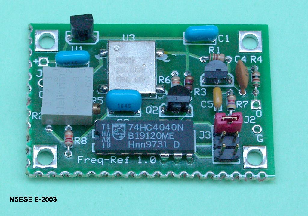
Here's a picture of what you get for your hard-earned 17 smackers:
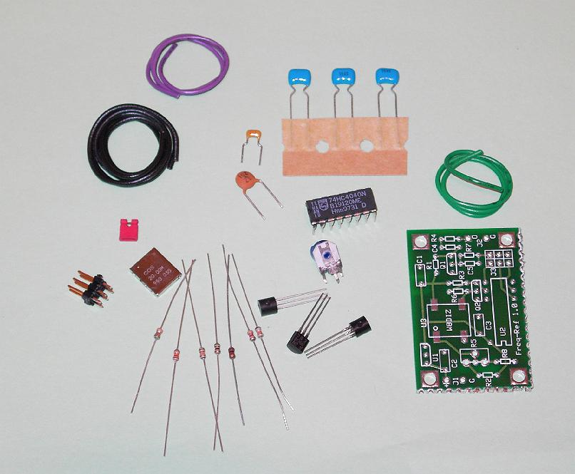
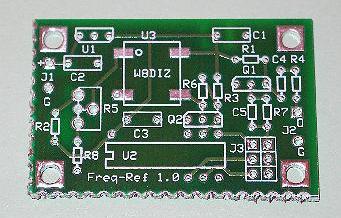
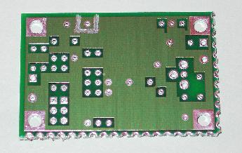
As you can see, there are not a lot of parts, but a few are worthy of comment. The key component is the TCXO oscillator. That's the metallic box just to the left of the resistors. It's a 4-pin surface mount device. Not to worry, you smd-phobes, that's the only surface mount part, and it's a snap to install. Also notice the PC board. This is a double-sided board with plated through holes. It's not the prettiest board I've ever seen (it has a mistake corrected on the bottom, which you can see corrected in the image below, and rough edges on two sides), but it's perfectly functional. If you pride yourself in making ugly things work (or making things that work, ugly), you'll have no problem with these boards. Here are some pix of the bare boards, top and bottom:
Parts assembly is semi-straightforward, but be forewarned - you don't get printed instructions with this. Wait, don't panic! - you can download them from the internet site, and print them at home (3 pages, including schematic). There is one really odd thing about mounting the 74HC4040 DIP IC - there are no holes drilled in the PCB for the unused outputs, so before you mount the IC, you need to cut or break off those pins. The risk here is that you'll count wrong and cut off the wrong pins, then end up having to wait for another chip. Diz has a semi-sound reason for doing this - he wanted to avoid radiating from the unused output pins. Hmmm. Here's the completed assembly, before mounting in an enclosure:
Those with sharp eyes will note a modification on my version. To make setting to frequency a little easier, I mounted a 10-turn pot in place of the single-turn pot provided. This meant that I had to move one of the resistors to the bottom. I wouldn't call this a required mod, at all. If I hadn't already had the pot in my junk box, I would have been quite happy with the one provided by Diz. I also had a bad 2N3904, which had to be replaced in the output circuit, again from my junk box.
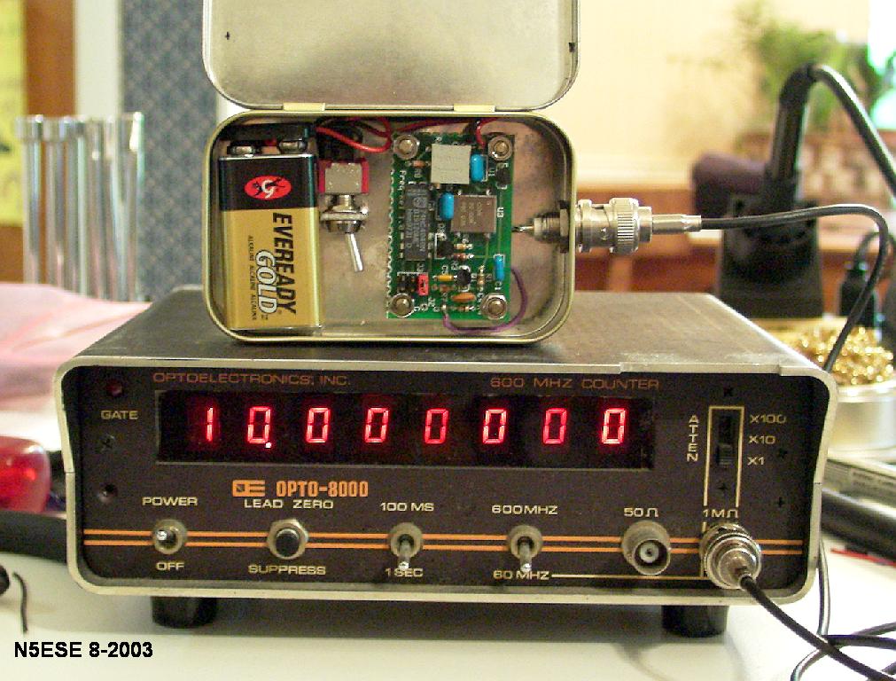
I decided to mount mine in a - what else? - Altoids tin. There's more than enough room for the board, a switch, a BNC connector, and a 9 Volt battery. You can see the finished product in the image at the top of the page. The switch is mounted in an unusual way. I took a piece of 5/8 x 5/8 inch double-sided scrap PCB, drilled a 1/4-inch hole in the middle of it, and soldered it directly to the inside of the Altoids tin. Then I mounted the switch. This way, the switch is not sticking out of the Altoids, waiting to be broken off or switched on accidentally. Really, the switch is not even necessary - you could just as easily connect or disconnect the battery, to turn the unit on and off.
How does it work?
Actually, it works quite nicely. It drifted about 4 or 5 Hertz in the first minute or so. Diz recommends a 10-minute warmup before setting it, but I didn't note any drift after the first minute. Thereafter, the unit holds its frequency pretty well. I was able to set it to within 0.1 Hz of 10.000 MHz using a ten-second gate on a calibrated lab-grade frequency counter, and it stayed within 1 Hertz for the next two hours. Letting it cool, and turning it on again, it settled to within 1 Hz of its former frequency within a minute. I hit it momentarily with a heat gun, to simulate a small temperature change, and it maintained its frequency within 4-5 Hz. Pretty good stability for a $17 reference oscillator.
Diz suggests zero-beating the oscillator with WWV on 10 or 20 MHz. I tried it, and it ain't as easy as it sounds. When I did it, I thought I had it zero beat, and it turned out to be about 11 hertz off frequency. I think I may have been beating against one of the sidebands of WWV, or else against a shortwave broadcast carrier that was almost on top of it. Or else, I was overloading my receiver. Anyway, I finally ended up taking it to work and adjusting it against a calibrated instrument. Subsequently, I've been able to tweak my bench counter (at home) and several CW annunciators to much closer tolerances, using the Frequency Reference as a known source.
Current draw meausred 26.5 mA from a 9 Volt battery, which means you'll be changing that battery fairly often if you forget to turn the unit off.
Bottom line? If you have need of a cheap-and-dirty frequency reference, this kit is the one for you.
73,
monty N5ESE
P.S. A PDF Version of the Frequency Standard Kit Instructions, provided by Jon, EA2SN, and including the schematic, can be found - here -