N5ESE's RF Inductance Meter
(click on any picture to see larger version)
I'm always looking for cheap and simple ways to accomplish tricky tasks. As an RF homebrewer, I frequently wish I had a way to reliably measure inductors I wind for projects. Most of my homebrew projects are in the HF range, that is, 3- 30 MHz. Most commercial inductance meters, however, use low frequencies (less than 100 KHz) to measure unknown inductances. This is probably adequate for air-wound coils, but as many have found out the hard way, not too accurate for toroidal-wound or slug-tuned inductors designed for RF. The effective permeability of these core materials are optimized for RF frequencies, and don't respond the same when low frequencies are applied to them.
Presented here is a "Saturday" project I built from parts already in my junk box. Had I bought them all new, I estimate the cost would have been less than $35. The L-Meter here measures inductors in the range 0.15 thru 65 uH, and uses signal sources in the HF range that are suitable for measuring toroidal or slug-tuned inductors generally found in ham radio circuitry in the 80 - 2 meter range (as well as air-wound or form-wound inductors). It will not measure audio or IF inductors, but I find that those are not the ones I'm usually trying to measure, nor are they the ones that usually cause me problems.
Theory
There are many clever methods that have been devised to measure inductance and capacitance, but I wanted to go back to a tried-and-proven traditional method, and put a new twist on it. Here's a block-illustration of what we'll try to do:
Recall that when an inductor and capacitor are placed in parallel, they form a resonant "tank" circuit, in which the impedance (resistance) across the circuit becomes very large at the resonant frequency. This means that relatively little AC current will flow through the circuit at resonance. As the frequency moves off-resonance, however, either the capacitor or the inductor tend to allow AC currents to flow around the circuit. If the frequency is above resonance, the capacitor is the culprit, and if below, the inductor. We'll exploit this property to design a simple L-Meter (Inductance Meter).
Referring to the block diagram above, lets imagine that we apply a single frequency sinusoidal source (left) to a series circuit consisting of a parallel tank circuit (C-TUNE, our tuning capacitor, and Lx, our unknown inductor) and a light resistive load (R-L). If we have a fancy-dancy RF Voltmeter (a good Oscilloscope would be a great way RF Voltmeter), we would measure the voltage at the load resistor (R-L). Most of the time, the voltage would be fairly steady, something less than the applied voltage from our source, but not a whole lot less. Provided that we have enough range on our variable capacitor to resonate with Lx, as we tuned our capacitor from one end to the other (i.e., maximum to minimum, or vice versa), we would notice that there is one unique capacitance setting where the voltage across the load resistor drops way, way down low. If our RF Voltmeter were a true meter, rather than an oscilloscope, we would see a pronounced "dip" of the pointer as we passed through resonance. By the way, if we never saw a dip, it would probably be because our inductance is too small or too large to resonate with the range of capacitances our tuning capacitor provides.
If we knew exactly what capacitance we had when we reach the lowest "dip", we could use the formula shown to calculate the unknown inductance. We would simply plug the frequency (in Hz), and that exact capacitance into the formula, do our calculation, and presto!... we know our inductance. Here's an example: let's say we have a source generator of 5 Volts peak-to-peak at a frequency of exactly 10 MHz. Lets say our tuning capacitor (including stray capacitances, you sly dawg) will vary from 25 to 225 pF. We watch our RF Voltmeter, which seems to read in the neighborhood of 2.5 Volts when we have our tuning capacitor at minimum. We slowly turn our tuning capacitor, while watching the meter, and about midway we see the voltage dip way down to almost nothing. We set the tuning capacitor right there, where the dip is deepest. Our dial tells us that the capacitance is 120 pF. Now we have enough information to calculate our unknown inductance:
We could take it one step further to figure out the range of unknown inductances we could measure, because we know the minimum tuning capacitance is 25 pF, and the maximum is 225 pF. Plugging those two numbers (min and max C, separately) into the equation, we come up with a range of roughly 1.1 - 10 uH.L = 1 / ( 4 * PI * PI * 10,000,000 * 10,000,000 * 0.000000000120)
= 1 / (4 * 3.1416 * 3.1416 * 10E06 * 10E06 * 120E-12) [calculator notation]
= 2.11E-06 [calculator notation]
= 2.11 uH (microhenries)
That's a fairly useful range for RF homebrewing on 40-20 Meters, but we'd like a little bit more and a little bit less, for the lower and the higher bands. One thing we could do is switch to half-frequency (5 MHz) or double-frequency (20 MHz), while keeping the same capacitor. When we do that, we come up with a Lx range of 4.5 - 40 uH, and 0.3 - 2.5 uH, respectively, or a total measuring range of 0.3 - 40 uH. Now, that's useful!
OK, But What 's the "Gotcha" ?
There are always "gothchas", but they're fairly minor in this case.:
Let's dismiss the first three challenges in short order:
- I don't want to dedicate my signal generator to this task
- I don't have an RF Voltmeter nor an oscilloscope
- I want to use parts in my junkbox, if possible
- And the "Biggee": I don't know the capacitance on my tuning capacitor at every point along the dial
We'll use el-cheapo CMOS/TTL crystal-controlled clock generators as sources. I'm talking about the type that are used to drive microprocessors, and which are made by the gazillons so that they are dirt cheap (like, less than $4 each). Turns out the frequencies we've already talked about are standard manufacture, so they're cheap and readily available. But wait, you say! Those clock modules have square-wave output. Not to worry, we'll add an R-C filter at the output of each clock, to reduce the harmonics enough that we'll get no false dips. That's all it will take... one 5-cent resistor and one 10-cent capacitor. That will reduce our output slightly, but there is plenty enough output capability in the clock chips to take care of our needs, even with the extra filtering. Of course, we'll need to select the values judiciously, to accomplish the correct filtering action, but even that is plus-or-minus 20%, so no big deal at all.
We'll use one of the cheapest, most reliable RF Voltmeters known to technology - the diode detector. Talk about simple - two germanium diodes - 10-cents apiece plus a cheapy DC micro-ammeter. If you don't already have the meter in your junkbox, buy one from a surplus/electronic clearance house, or steal one from a cheap junk voltmeter... I think we can live with the shame.
Please DO use parts in your junkbox. I pulled the clock modules I used out of old castaway modems. They've been sitting in the j-box for years, waiting to be used. Use whatever variable capacitor you have. I used some polyvaricons I bought years ago from someone on the QRP-L mail-list. They had one shaft but two sections, and were very tiny, about 1in x 1in x 0.5in. I paralleled the sections to come up with the range we talked about. You could scrounge from an old table or pocket AM/FM receiver, or use that swapfest variable cap you couldn't resist buying 10 years ago. (I've been there, too, compadre). I used a 0-250 microamp edgewise meter I bought from Dan's Small Parts. Originally, the scale was intended to read S-units (probably for a Chicken-Band radio). Scale makes no difference at all here, because we're only looking for a "dip" in the reading. Probably, any panel meter with a sensitivity of 0-1 mA or less will work just fine.
Ah, yes, the "Biggee". How do I know what the actual capacitance of my tuning capacitor is? This is the biggest challenge of the project, but it's really not that big. You could use the exact same capacitor I did ( a polycon variable with two sections, nominally 60 and 160 pF max, respectively). If you do, you'll be able to "copy" the dial I used and get reasonable accuracy. Sorry, but I'm just not sure where I got it, nor of it's exact specifications. If it helps, it has a "TT" logo impressed on the plastic case, and the letters "TTWM", which may be a series number. It also has a "7" impressed on the front. I'm pretty sure it was the same one used on the NorCal BLT tuner kit, but I can't swear to it.
But the best thing to do is measure it, and it turns out measuring capacitance of a variable is even easier than measuring inductance, but you do need to do it accurately. In recent years, lots of handheld digital multimeters have had capacitance measuring capability on them. Alas, they usually will not accurately read capacitances less than 1000 pF. Frankly, I've found my gizmo Junkbox Capacitance Checker to be very accurate down to 10 pF or less, and can also account for stray capacitances. It's another Saturday project, but one you'll be glad you took on. Otherwise, you can visually determine the capacitance if -and only if - the rotor plates are semi-circular, and if you know the minimum and maximum capacitance. Often, the min/max is published by the manufacturer. If you make a dial with even divisions, then you can determine the capacitance at each setting.
How'd You Do Yours, Smarty Pants?
I mounted my capacitor in the junkbox cabinet (minibox), and wired it up minimally with the clips I was going to use for attaching the unknown inductor. This way, I could include any stray circuit capacitances. If you have integral trimmers on your capacitor, set them to about mid-point. I then went to my PC, and built a scale marked in 10 degree increments from 0 through 180 degrees. You could just as easily do this by hand also, using pen and paper and protractor. I improvised a dial pointer using a sewing needle and a knob. I set the tuning capacitor at 0, then 10 degrees, then 20, etc, and measured the capacitance at each setting, keeping a log of same. Don't forget to subtract (or null) the stray capacitance of your capacitance measuring device, but don't subtract the stray capacitance of the L-Meter circuitry.
Once I had accurately measured the capacitance of my tuning circuit (sans unknown inductor), I interpolated between the 10 degree steps to get the capacitance at each 1 degree increment. At this point, I could have stopped, because if you know the capacitance at any given setting, you can use the formula to determine the unknown inductance. But I wanted to fancy it up a tad, plus make things easy on myself during future homebrewing projects. I wanted to construct a tuning dial that was calibrated directly in micro-henries. So I plugged the capacitance values into an electronic spreadsheet, and let it calculate the inductance values for me at each 1 degree increment, and for each of the three source frequencies. If you want to use the same spreadsheet (MS Excel v4), click -here-. Now, using a CAD drawing program (AutoSketch v2.1, in my case), I marked the dial in reasonable measuring increments, not in capacitance, but in micro-henries (corresponding to the value found in the formula based on the capacitance and frequency). What resulted was the dial you see in the pictures, available in MS Word (v6/97/2002) -here-, if you're using the same capacitor. To the degree you measure the tuning capacitor accurately, and account for stray capacitances, and construct the dial with care, you'll get an instrument that measures with amazing accuracy (say +/-5% or better).
On With Construction
Here's a schematic of our version:
Keeping with the KISS principle, we used whatever we had available for construction. You should do the same. Really! Parts are extremely non-critical.
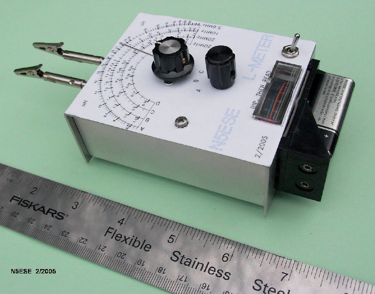
A few years ago, we had purchased some mini-box type cases from TenTec (who manufactures enclosures, if you didn't know) while they were on sale. They sat on the shelf gathering dust for years, until I got this wild hair to build an L-Meter. The case is a two-part U-construction aluminum type, approximately 4 x 3 x 1.5 inches. If you want to duplicate my construction, I think you're out-of-luck, because this box was discontinued (which is probably why they were on sale HI HI). No matter, anything that size or bigger will do the trick, or build it on a hunk of cast-off plywood.
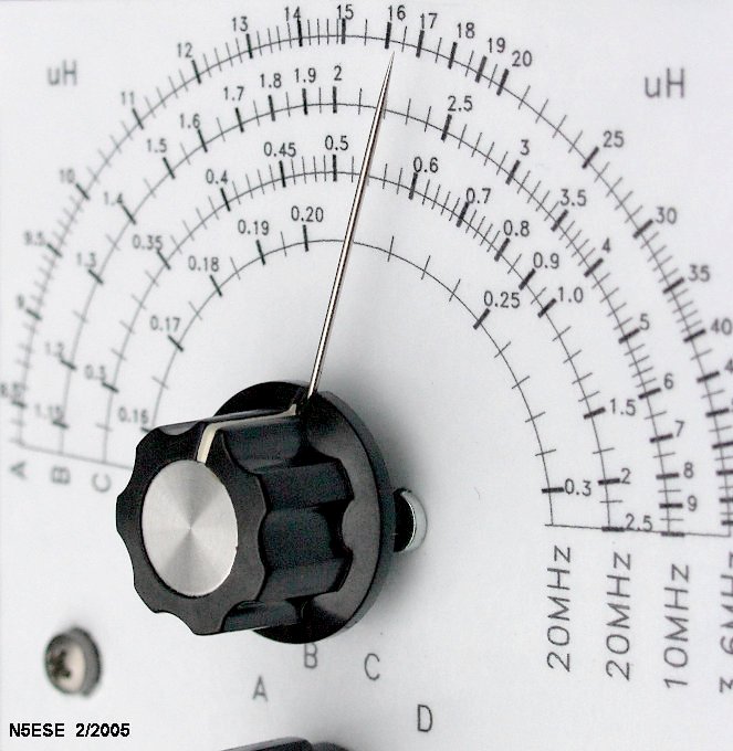
The dial pointer was built out of an available bakelite knob, into which I carefully drilled a 0.032" hole (using a carbide drill) laterally into the knob skirt. Then I "found" a sewing needle that would just fit into the hole, blunt end first. Between the Ballpoint RF Probes and this and other projects, the XYL's stash of sewing needles has gradually been dwindling... so far, she hasn't noticed...
Here's a picture of the dial pointer and the dial (described earlier):
The dial and front panel label was made on the PC, and printed onto "sticky-back" paper (mailing labels, full-sheet size, available at any office supply store), onto which a "sticky-back" clear laminate was applied. Of course, the front panel part will only apply to my enclosure, but you can download it in MS Word (v6/97/2002) format -here-, if you want to print and cut and paste from it.
Except for the front-panel mounted parts, components were mounted on perf board, then wired super-ugly style to the DP6T rotary switch, which I had picked up at a recent swapfest. If you wanted to skip the rotary switch, and are happy with just two ranges, you can use a DPDT toggle switch. Here's a gander inside:
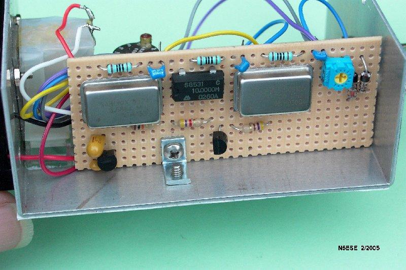

(click on the picture to see larger version)
Keeping the wiring loose, not bundled, is ugly but it helps to reduce stray capacitance. Really, that's my story and I'm stickin' to it...
As I mentioned before, we used what we had, and we used clock modules that we had pulled out of old modems years ago. Instead of 5 MHz, we used 3.6864 MHz, because that's what we had, and the dial we constructed reflects that choice. Turns out, we still had a nice overlap between ranges, which is what we were trying to acheive.
The clock modules run on 5 volts, and I wanted to run off a 9 Volt battery, so we had to knock that down to size using a three-terminal regulator. The 78L05 is a cheap TO-92 package device, but it's quiescent (idle) current is about 5 mA, which means we needed an ON/OFF toggle switch to save the battery. If you substitute one of the micro-powered regulators (like the LP2950 or LP2985), you could dispense with the switch, and simply turn the rotary switch to an unused position to turn off the unit. By the way, the clock modules will eat up a 9 Volt battery in a few hours, so only turn on the unit while you are making measurements. No warm-up is required.
As you can see from the pictures, the 9 Volt battery was mounted outside the case, to facilitate easy change-out.
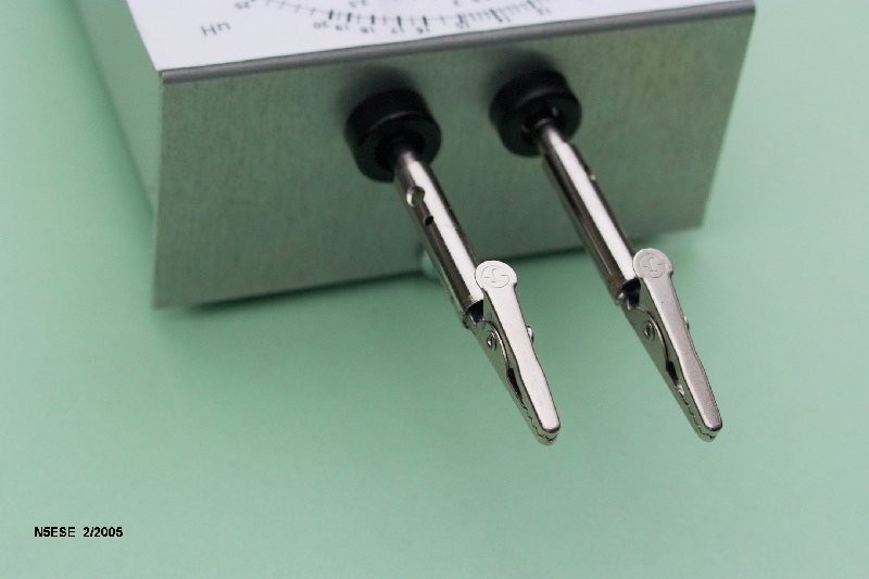
Two banana jacks were mounted on 0.75" spacing at the top of the box, and form the connector to the unknown inductance. We built clips for attaching the unknown inductance from alligator clips and banana plugs, removing the insulation from the banana plugs, and soldering the clips to the plugs. The alligator clips assembly, then, is easily removed, and another assembly can be fabricated for say, surface mount inductors. Here's a picture of that end of the box:
Finished out, the front panel looks like this:
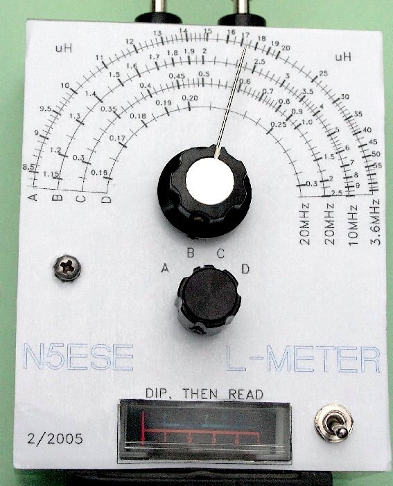
As you can see (above), the needle dial is readily and precisely readable. Protecting the dial's needle is an issue I haven't addressed yet, beyond putting it in a box. If you have any clever suggestions, please let me know.
Yeah, yeah - but does it work?
Oh yeah, it works. I haven't compared it to a lab instrument, and I have no precision inductors in my junkbox, but I took a sampling of 5% commercial inductors from my junkbox, and measured them using the L-Meter, and was pleased to find that all read within tolerance, from as low as 0.47 uH to as high as 47 uH. We were able to measure inductance over the full range for the three ranges we implemented, covering 0.3 - 65 uH, and we got good deep dips on everyone we tried. We also searched for false dips, and found none of any significance whatsoever.
In the schematic, you'll notice some components marked with an asterisk (*). These have not yet been implemented, and will form range "D". Here, we'll add a 180 pF 1% silver mica capacitor in parallel with the tuning capacitor, and only on range D (20 MHz). We could implement this with a SPST switch, but there's not a lot of room left on the front panel. Thus, the proposed relay. We'll see how this develops, but hopefully, this will allow us measurements down to 0.15 uH. This should be suitable for RF circuit development into the lower VHF range (6 and 2 Meters).
We took the meter to "show and tell" at the local QRP Club meeting, along with a handful of inductors, and everyone had a blast finding the inductance and sorting them out. There's something intrinsically satisfying about "dipping" meters, that we rarely enjoy with modern Ham equipment..
73, and enjoy! monty N5ESE