M-Cubed FPM-1 Frequency/Power Meter
(click on any picture to see larger version)
(click on any picture to see larger version)
I was recently quite fortunate in being invited by the designers at M-Cubed Electronics to participate in the beta-build of their FPM-1 Frequency/Power Meter Kit. It is due to be announced the weekend that I write this (Nov 18, 2005), and I want to get a review online immediately, to let prospective buyers know what I thought of it. So, to make a long story short:
WOW !
This is a pretty cool little portable instrument. It has more functionality than most instruments in this cost range, the feature set is amazing, and the ergonomics are first-rate. It measurement accuracy rivals laboratory equipment, at far, far fewer dollars. And anyone with a modicum of soldering experience will find it easy to assemble. (Note, it may not be for the beginner).
So, What Is It, Already?
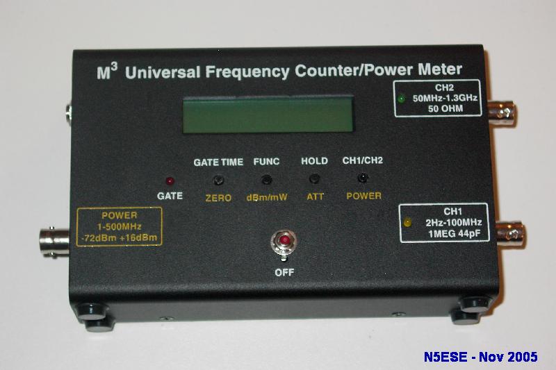
It's really two instruments in one compact package: a sensitive, wide-range frequency counter, and a versatile, wideband RF power meter.
First, it's a first rate frequency counter, capable of measuring frequency up to 1.3 GHz (!!!) to within 2 ppm or better, and with 7 significant digits of display resolution. Two inputs are provided for frequency measurement. Input Port 1, the high-impedance input, measures from 2 Hz to 80 MHz. Because the counting method employed uses the "reciprocal" technique, readings taken at low frequencies enjoy the same 7-digit resolution as higher frequencies. That is, not only can you measure a 20 MHz signal with 10 Hz resoluttion, you can enjoy the same 7-digit resolution at, for example, 2.467224 Hz. Input Port 2, with a built-in prescaler to cover frequencies up to 1.3 GHz, is a low-impedance (50-ohm) port.
Secondly, it's a wideband RF Power Meter. And not just any run-of-the-mill power meter. This meter can accurately measure over a frequency range from 1 to 500 Mhz, and is usable up to 800 Mhz! This meter has a typical measurement dynamic range of 88 dB or more, measuring from -72 dBm to +16 dBm to within 1 dB, with a display resolution to 0.1 dB. Let's put that in perspective. -72 dBm is 63 picowatts (!!!) which is an 'S9' signal into a ham receiver. +16 dBm is 40 mW. Now, you may be thinking to yourself, what use is that? But if you do any homebrewing of RF circuits, I'm betting there were many, many times in the past when you wished for more range (freq and power) than your RF Probe. And you probably wondered if you could even trust a low reading on your RF Probe. Wonder no more.
With the addition of a simple external attenuator, which can be built for less than $10, you can extend the range of this meter to nearly 400 Watts. That's a compounded measurement dynamic range of over 130 dB. Amazing! Think of it, with the attenuator, you could measure from less than a microwatt to 200 Watts, with typical 0.5 dB accuracy, over the entire HF and VHF range. That's really a lot of measurement capability.
Measurement capability aside, it's really the feature set built-in by the skilled programmer(s) at M-Cubed that makes this instrument such a pleasure to use. Let's give an example or two which are especially useful for those who like to build and test RF circuits and radios, like myself.
Cool Feature No. 1 - Ergonomics
The first thing you notice when looking at the FPM-1 is the neatly arranged front panel, with the large (2 lines x 16 character) LCD, and 4 small pushbuttons. Above the buttons, in white silkscreen, lables which apply upon default power-up functions. These are "base-level" functions. Below the buttons, in yellow silkscrren, are the base-level functions for the power-measuring mode. But there are many internal menus for selecting functions, making adjustments, and setting memories. These internal menus show up as software lables on the bottom line of the display, right above the hardware buttons.
For example, if we push the rightmost button (CH1/CH2), we get the following display:
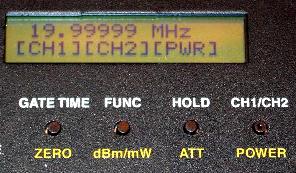
On the bottom of the display, the three lables [CH1] [CH2] [PWR] refer to the current function of the three leftmost pushbuttons, indicating that the current button functions select Frequency counter Channel 1 (0-100 MHz), Frequency Counter Channel 2 (50-1300 Mhz), or the Power Meter. This is the manner in which you select which function (and BNC input jack) is active.
Of course, there are many more functions, which can be found in the documentation... and that leads me to:
Cool Feature No. 2 - Documentation
The staff at M-Cubed has done a superb job of documenting the FPM-1. It begins with the Assembly Manual (this is a kit). Being a Beta-Tester, I expected to see lots and lots of errors. There were surprisingly few to begin with, and they were readily corrected, resulting in assembly instructions that are illustrated with pictures wherever any uncertainty exists. And, of course, clear schematics, parts lists, and board outlines round out the package.
The operating (user) manual is nothing short of superb. Each function is accurately and clearly documented, and each menu panel is illustrated. I read through it once, practicing each mode as I went along. After that, the menu functions seemed intuitive and natural, meaning I no longer needed the manual.
Cool Feature No 3 - Frequency Measurement Flexibility
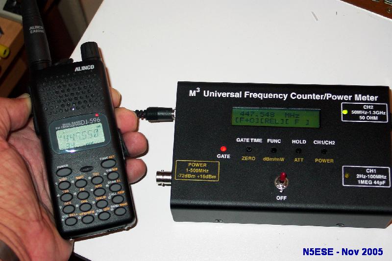
On either Channel 1 or Channel 2, you can select to measure either frequency or period. To support frequency measurements, you can also select gate time as 0.1, 1, or 2 seconds (which affects resolution and display update rates inversely). Here's a picture of the FPM-1 measuring the frequency of my dual-band HT's transmitter on the 70 CM band, through a short antenna connected to CH 2:
On Channel 1 only (0-100 MHz), you can also Totalize (i.e., count pulses), and measure Pulse Width and Duty Cycle.
A really cool feature of frequency measurement, as a result of having a microcontroller onboard, is that some internal calculations can allow some very useful features to be implemented, based on the frequency count. One I found particularly intriguing is the ability to set a measured frequency as a reference (i.e., display it as zero). What then results on the display is a measure of the difference. This is perfect for measuring drift in a VFO or crystal oscillator, for example. Turn on the oscillator cold, get the initial measurement, go to the HOLD submenu, Press MOD, then F-O (meaning 'Frequency - Fo'). The unit begins to measure the frequency as usual, but now displays the deviation from the original "held" frequency. Now it's an easy task to observe the drift over time.
As an aside, one need not worry about the internal reference oscillator drifting. It's a TCXO, and after about 10-15 minutes warm-up, should be +/- 1ppm of it's nominal frequency. That's a good, stable oscillator.
The FPM-1 can also be used as a display, with offsets and difference modes to accommodate the conversion scheme of any superhet receiver. Just drill down into the HOLD | MOD submenus (the manual explains this quite succinctly).
The frequency counter's sensitivity is very usable across the entire range, and the triggering is remarkably insensitive to noise. I found that I could hang a 12-inch BNC antenna on either input, and easily measure the frequency of the radiated signal of my QRP HF rig, and my Dual-Band HT.
Cool Feature No. 4 - Power Measurement Flexibility
As we mentioned earlier, the power metering is state-of-the-art: excellent sensitivity, good accuracy and resolution, wide measurement dynamic range, and wideband capability. For straight-ahead power measurements from -72 dBm to +15 dBm, it simply can't be beat - that is, without spending a kilobuck or two.. But where it really shines is what you can do with that to make it even more useful.
Once again, it's the presence of a microcontroller (with some really top-notch firmware) that's makes these extra features possible. Take frequency compensation, for example. The RF power metering mode covers the range from 1 MHz to 500 Mhz, and is rated to within +/-1 dB across that range. One of the reasons that's possible is because a correction is applied to the raw measurement (before it's displayed), based on the frequency the power meter believes is applied. Now, the power meter doesn't really know what the frequency is, unless you tell it, and there are a few ways to do that. One way is to measure a frequency (in counter mode, at input 1 or 2), and then press HOLD. Now, when you switch to RF Power mode, that frequency is retained on the display, and in memory, for use in determining the correction to RF power. Cool!
Another way to tell the RF Power Meter what frequency it's at, is to select a value stored in one of ten memories set aside for that purpose. You can set those memories individually, either by measuring an actual frequency, or keying it in with a very clever method using the front panel buttons and prompts on the display. I set my ten memories to the center of the each major ham band from 3.5 MHz to 440 MHz, because those are the frequencies, as a ham, that I'm most likely to measure. Now, when I want to measure the power on my QRP rig, I just "recall" the band's center frequency, and go to power mode. Awesome! Takes just a few seconds.
Another supercool power meter feature is the ability to correct the displayed value for external attenuators and amplifiers. Let's say that you're probing a front-end receiver circuit using an amplifier with +13.7 dB of gain. Using the ATT submenu, you can set the "attenuator" offset to any value from -40 to +40 dB. In fact, much like the preset frequencies, you can store up to ten attenuator values in memory, for recall at will. In our example, the power meter would now account for the +13.7 dB of external amplification, and display the power at the input to the external amplifier (rather than the input to the power meter). Very Cool!
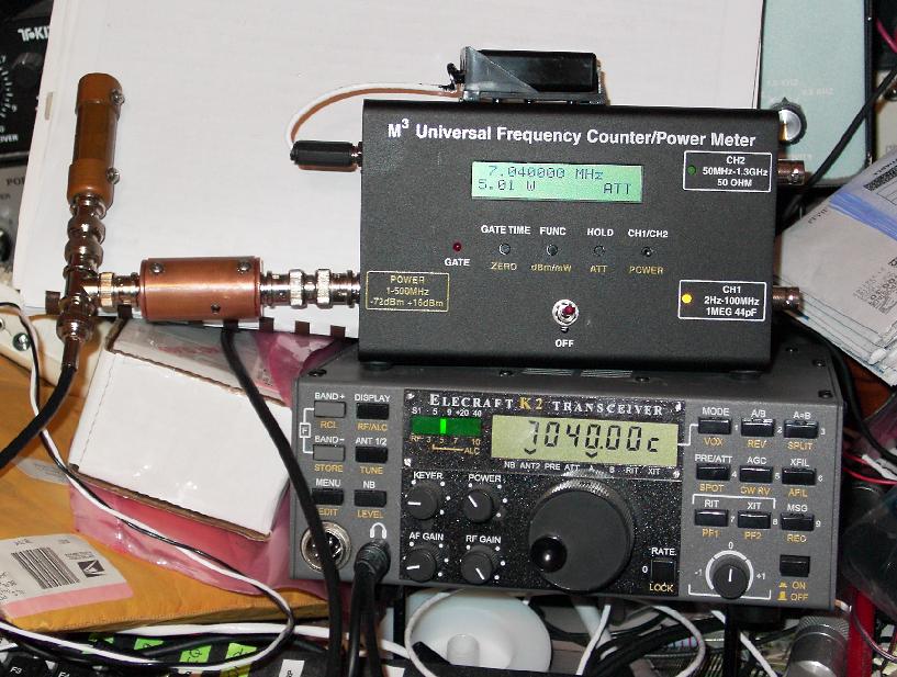
The way I find this feature most useful is in measuring the output power of my ham transmitters. To do this, I use the 40 dB tap attenuator I mentioned earlier, tee'd off from an external dummy load. Then, I set the ATT feature for 40.1 dB (the actual attenuation of my tap attenuator). When I subsequently transmit, I measure the actual transmitter power +37.0 dBm, in spite of the fact that the FPM-1 is only capable of measuring to +15 dBm. Radical!
But wait, there's more. I can't stand reading my transmitter power in dBm, so do I have to carry a calculator? Nope! I press the dBm/mW button on the front panel, and the FPM-1 does that for me: 5.01 watts. Yeah, baby! Here's a picture of it doing exactly that:
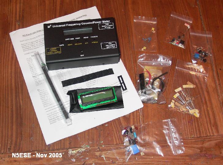
Kit Construction
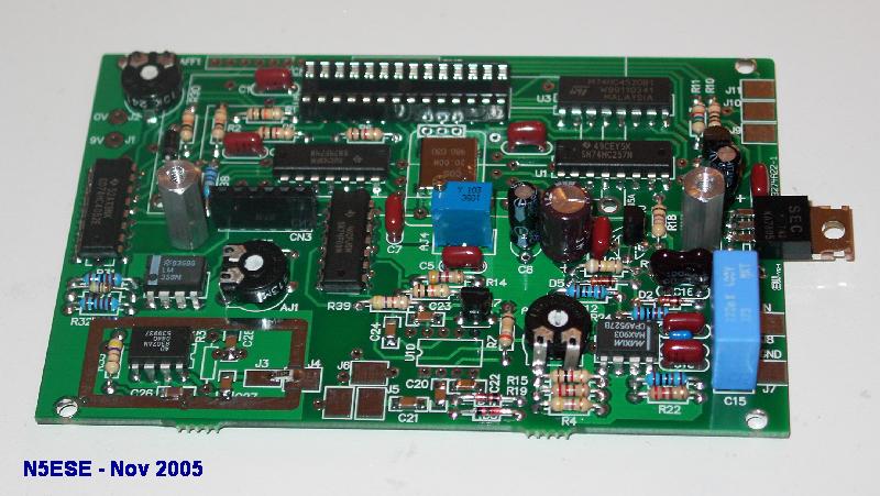
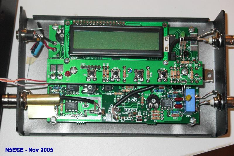
This is a pretty simple kit to assemble, but I wouldn't recommend it for beginners. Otherwise, the average kit-builder, with a modicum of patience, should have no problem. There are two high-quality (silkscreened and masked, with plated-thru holes) printed circuit boards, and the pre-fab display assembly to contend with. For those who are SM-phobes, surface-mount IC's come pre-mounted,. It's pretty straight-forward assembly. There's a lot of electronics in that box, and it goes together pretty nicely. There are very few potential amiguities in the assembly instructions, and those few tricky parts are now illustrated with clear diagrams and photographs.
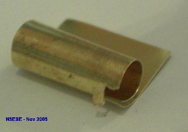
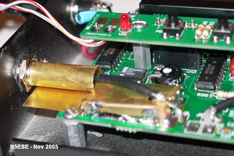
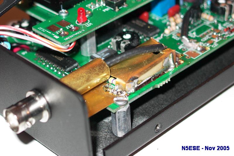
Probably the trickiest part of the assembly - and also most critical to performance - is the installation and soldering of the RF Power input coax ( three-inch piece of RG-174) and the brass shields which cover that cable and the AD8307 power detector chip circuitry. The brass shield must be cut and bent carefully, as explained in the manual. It requires a bit of mechanical finesse, something I'm not exactly renowned for. I had to do my shield and coax twice before I got it right, and managed to break the fragile input resistor in the process. All's well that ends well, and as a result of my fumbling, a few more explicitly detailed instructions and pictures appear in the assembly manual ;-)
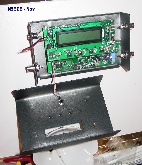
There is some point-to-point wiring from the main board to the various connectors in the enclosure, and to the power switch. It is best to fully test your unit functionally before you solder-in those BNC connectors or solder-mount the shields, because once they are mounted, you can't get to the bottom of the main pc board to do troubleshooting or remove components. That point is perhaps NOT clear in the manual, and I learned the hard way how to swap out a DIP chip in close quarters from the TOP of the board. It warn't easy!
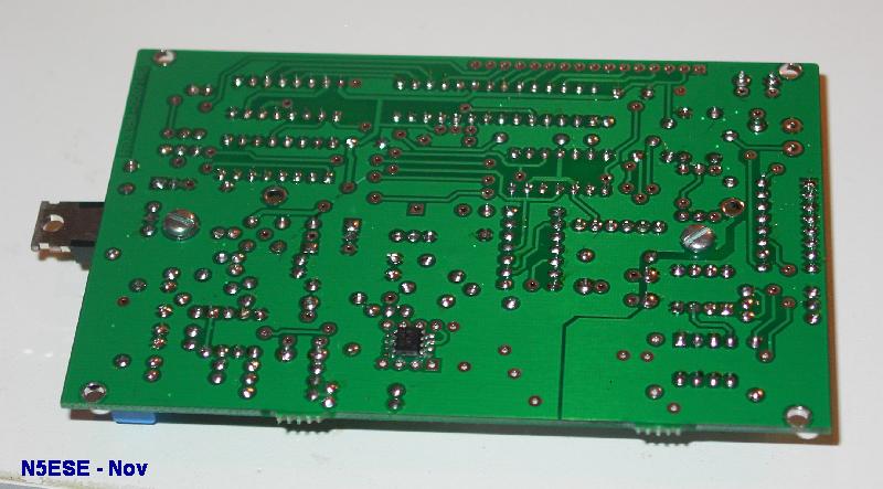
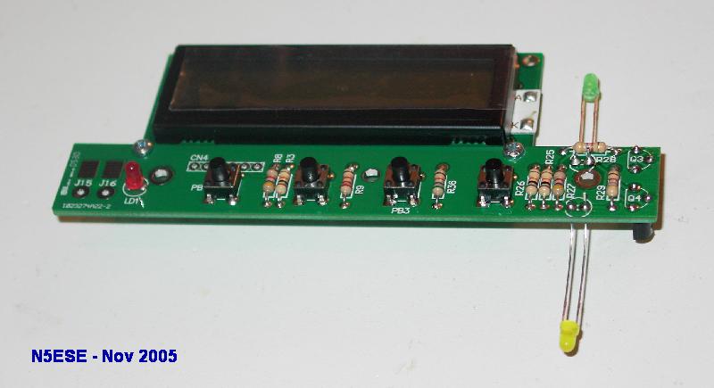
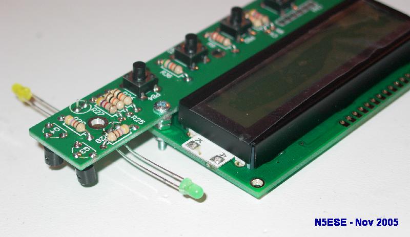
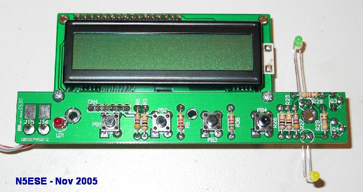
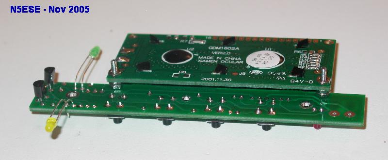
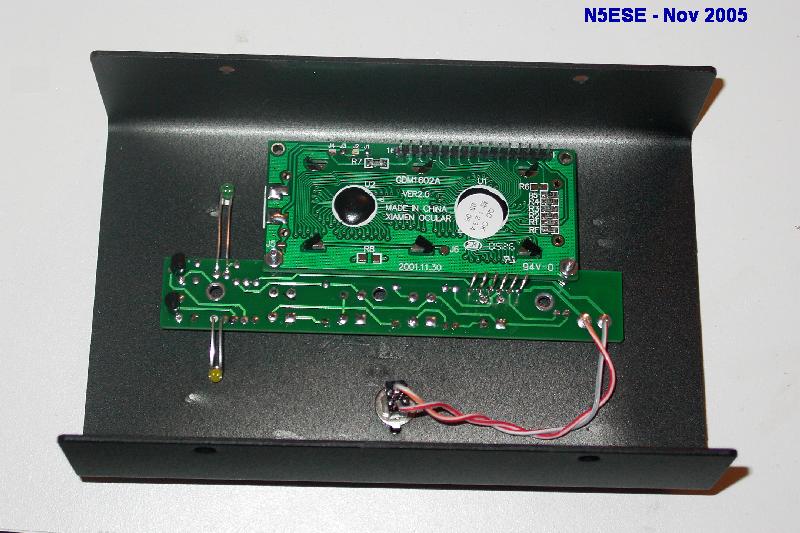
At the bottom of the page, I've included links to various pictures of the internal workings of the FPM-1. Be aware that this was a beta build, and although it's substantially the same, you shouldn't be following my construction too closely.
Calibration Procedures
The FPM-1 requires calibration to set the "slope" and "intercept point" of the logarithmic power detector, and also to tweak the internal reference (20 MHz) TCXO oscillator to exact frequency. I suppose it's the "catch-22" of test equipment that, in order for it to measure accurately, you need good test equipment to calibrate it. In order for the frequency counter to measure accurately, you need to set the reference oscillator accurately. And in order to set the power detector accurately, you need two accurate reference points. Sigh.
If you have lab grade equipment suitable for use as a secondary standard (i.e., for calibrating other equipment), I'm not sure you would need this piece of equipment in the first place, unless for it's relative small size. Sure, you can use cruder equipment or approximations for calibrating, but the accuracy will suffer. So, just what do you need? Well, M-Cubed wants you to tweak the reference oscillator using a 10 MHz input that's stable to within +/-2 ppm. That means either a very accurate signal generator (most aren't that accurate), or a signal source that can be tweaked to WWV exactly. Actually, the latter method is quite do-able, and will probably serve to get the reference oscillator adjusted to within a Hertz. M-Cubed offers yet another method, which I'll explain in a minute.
M-Cubed wants you to adjust the slope/intercept of the power detector based on two 10 MHz input signals which are known to be accurate within 0.1 dB (about 2%). The calibration procedure suggested by M-Cubed involves adjusting the slope so that a signal of 0 dBm and one of -30 dBm read 30 dB different (exactly), and then they store an offset in memory (as a fixed calibration factor) at 0 dBm. All well and good, if you have two accurate power sources. How many of us can be sure?
One solution would be to use a 40 dB tap attenuator of known value (like that described -here-) or, alternatively, fixed or stepped inline attenuators (also of known accuracy), and apply a higher power signal, like 5-10 watts, at the input of the tap attenuator. You could measure the higher power using an RF Probe (look -here- or -here- for examples) or an accurately calibrated Oscilloscope (I usually don't trust scope calibrations at RF frequencies). For example, with the 40 dB attenuator, a 30 Meter transmitter output adjusted to 22.4 Volts RMS at the dummy load would provide 0 dBm at the power meter input, for calibration. Thereafter, you just need a fixed 30 dB inline attenuator to get the second calibration point of -30 dBm. If you can tolerate a little reduced accuracy, you can do the second calibration point at -20 dBm, instead of -30 dBm. You can pretty easily build an accurate inline attenuator using 1% resistors, or build a step attenuator like the one shown -here-. It should be mentioned that the clever engineers at M-Cubed recognized that some folks would like to pick their own power calibration points, and a provision is included for setting the calibration offset at some power other than 0 dBm. Man! Those guys thought of everything!
They really did think this through... and to support calibration for those who don't have access to lab equipment, they offer an inexpensive Calibrator for the purpose. The M-Cubed Calibrator comes fully assembled and pre-calibrated, with its own TCXO tweaked to within +/- 1 Hz, and switchable power levels of 0, -10, -20, and -30 dBm, all accurate to within 0.1 dBm. Here's a picture:
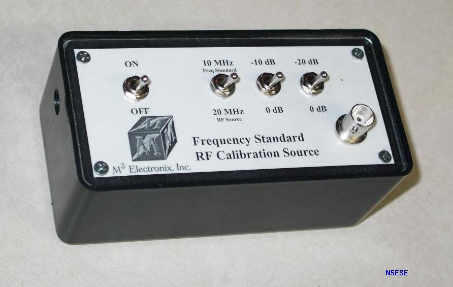
I took my beta Calibrator to work to put on a laboratory grade power meter, and found the 0 dBm output to be 0.08 dB off, and the other switch positions to be within 0.2 dB of their nominal settings. That's after traveling across the country via UPS to get here. Not bad!
Measured Performance
Except for some spot measurements on the ham bands from 160 Meters through 70 CM, I didn't do any stringent testing on the frequency meters. I found them, however to be quite robust across the range, and sensitive enough for virtually everything I tested them on. I saw very little evidence of false triggering; when I did, it was usually the result of a ground loop in the equipment lashup, which was apparent when it occured, and easily remedied. The same thing happens with my other (commercial) frequency counters.
I went to some trouble to evaluate the power meter, and as a result, I was quite impressed. For these tests, I used my Logimetrics 925 Signal Generator, which I believe has an attenuator that is accurate to within 0.5 dB across the measurement range of interest. It's specs are wider (+/- 1.0 dB for the attenuator, +/-0.5 dB for the leveling), but it seems to be much more accurate. Based on this, anyway, I conducted my tests, so you should keep in mind when observing the results that it is impossible to delineate any deviations as being from the power meter, or from the signal generator. That said, I still think the results are useful observations.
I looked at the overall measurement dynamic range, in an attempt to see what the basic measurement accuracy would be in real life. The M-Cubed spec is:
Said in terms of measurement dynamic range (for +/- 1dB accuracy), the manufacturer's spec is 85 dB typical, and 88 dB "maximum". On my beta unit, I found the dynamic measurement range at the calibration frequency (20 MHz for the beta units) to better those specs:
- "-72 to +16 dBm maximum (sic), typical -70 dBm to +15 dBm depending on frequency and calibration"
- "+/-1 dB (f < 500 MHz)"
Of course, the manufacturer's specs were over the entire frequency range, which I was unable to measure. I was however, able to measure from 2 to 80 MHz. Over that frequency spread, I observed the dynamic range to be at least as good as their specified "typical" measurement dynamic range. In my measurements, I also observed a phenomenon that degraded the low-level accuracy when the frequency was below 2 MHz.
- 77 dB for +/- 0.5 dB (i.e., +/-12% power)
- 92 dB for +/- 0.8 dB (i.e., +/-20% power)
- 93 dB for +/- 1.0 dB (i.e., +/-25% power)
For charts of my actual measurements, and more detailed explanations and observations of the performance tests I did, look -here- for a white paper on that subject.
Mods... Already?
The FPM-1 is a compact unit that might lend itself readily to being portable, were it not for two factors. First, no provision is made for an internal battery. The manufacturer recommends no particular power supply, but provides a somewhat standard coaxial DC power jack (5.5 x 2.1mm, I believe), and specifies the power requirements as 9-15 VDC @ 200 mA. I found that a common (and compact) 9-Volt, 300 mA unregulated DC wall-transformer ("wall-wart") powers it quite nicely.
The FPM-1 is chocked full of electronics. As a result, it's a little power-hungry, but it's not quite that hungry ;-) During beta testing, I measured current consumption as 110mA @ 9.25 VDC with the LCD's backlight ON, and 55 mA with the backlight OFF. Fortunately, the clever design team at M-Cubed provided a means of turning the backlight OFF by choice or by default (from the factory, it's ON by default).
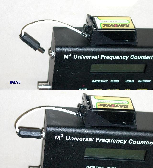
To make the unit more truly portable, I wanted to add a 9-Volt battery. Even on the bench, I hate having to deal with wall-warts. But I'd also like to be able to carry this instrument to the field. There are two problems regarding a 9-Volt battery:
I used a holder I got from FRYS (sorry, I forgot to write down the part number), but you can see a picture here:
Conclusions
Simple: This is a great kit-building project, and promises to be immensely useful around the shack. I intend for it to get a lot of use.
73, and enjoy!
monty N5ESE
Construction Pictures: