N5ESE's Experiments with Broadband Noise Generators
(click on any picture below to see larger version)
(click on any picture below to see larger version)
| NOTE: 'N5FC' is my former call. This project was constructed while that call was valid, and you may observe references to it. |
I'm always on the lookout for useful gadgets that make it simple to do a big job. Well describe a few such products on this page. We'll look at how a very simple RF noise generator can be used to measure receiver filter response, for off-the-air antenna tuning, for making antenna measurements, and for troubleshooting electronic circuitry.
Measuring Filter Response
Broadband noise generators have been around for a long time. If you're not familiar with them, you're going to be amazed at how simple they are to build, and how useful they can be around the shack, especially when used in conjunction with some recently available (but very sophisicated) software for PCs.
The noise generator is used to synthesize an RF signal which has noise components uniformly distributed over a very wide bandwidth. If the level is high enough above the self-noise of the receiver being tested, it provides a basis for some very practical measurements. If you were to look at that signal before it got to the receiver, with an RF Spectrum Analyzer (in the frequency domain, that is, amplitude vs. frequency), you would see a flat line indicating the amplitude of the noise, and it would span a large bandwidth (generally, much larger than the radio receiver's bandwidth). Alas, RF Spectrum Analyzers are relatively expensive, especially those capable of accurate measurements at receiver bandwidths. Rats!
If you were to feed such a noise signal into your receiver, and listen to it, you would hear a very loud hiss, and no matter where you tuned across the band, you would hear the same hiss sound. So what? What useful purpose can that have?
Well, if you can say definitively that there is a uniformly distributed RF noise signal coming into your receiver, and if you had the equipment to look at the frequency spectrum of the detected signal (coming from the audio output), you could measure the aggregate response of all the filters in your receiver. Hey! That's useful stuff, especially if your homebrewing receiver equipment.
Is it really that easy?
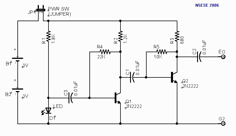
Here's the classic RF Noise generator circuit (solid-state version):
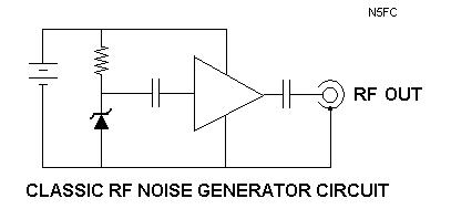
If you look at the first three components on the left, you'll recognize another classic circuit, that of the zener regulator. In that applicatioon, you allow a DC current to pass through a reverse-biased zener diode. The zener diode then regulates that current to a fixed DC voltage, as determined by the diode's reverse-avalanche characteristics (or "zener" voltage). All well and good. But look a little more closely, and you'll see something's missing - the output filter capacitor. While that's a very important part of a DC power supply, it's our worst enemy if we're building a noise generator. Somebody a long time ago decided to save a few pennies and leave out the filter capacitor, only to discover that the zener was generating a bit of broadband noise, all on it's own. But hey! That's what we're after. If we now pass that through a coupling capacitor (to block the DC component, which isn't useful to us), and feed it to a suitable high gain amplifier, we end up with useable noise at the output. And it turns out that the noise is quite uniformly distributed, with components from audio frequencies well into the VHF spectrum. Excellent! (By the way, the coupling capacitor is sized to allow RF to pass, but not DC or audio, but if you wanted an audio noise generator, you'd just size the coupling capacitor larger.)
The ampliffier can be any high-voltage-gain (40-60 dB, or x100 - x1000), broadband amplifier, with a low enough output impedance to drive the intended load. For our applications in ham radio, this usually means we're driving the receiver front end (50 ohms, typical). Is such an amplifier complicated? Not at all, as it turns out. Two or three 2N2222 transistors (at 5 cents apiece) and a few resistors are all that's required to build a suitable amplifier.
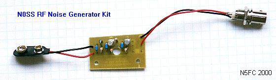
The N0SS RF Noise Generator
As if that weren't easy enough, along comes Tom Hammond (N0SS) and the Arizona ScQRPions. They provide a parts kit [alas, no longer available], including printed circuit board, to build just such a noise generator. All for $10. Yes, $10... CooOool! You provide a 9V battery (or other DC power source) and a way to get the signal to your receiver, and you're in the RF noise business! The original application for this kit was to provide kit builders a means of tuning the main bandpass filter characteristics on the Elecraft K2 transceiver kit. But (lucky for us), it works just as well for any amateur receiver!
Show-and-Tell
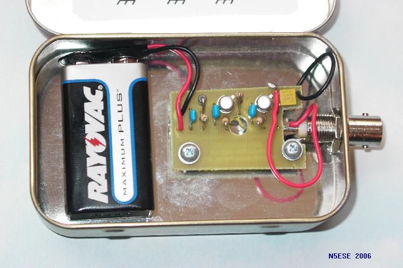
Here are some pictures of my version of the N0SS Noise Generator kit. I decided to package mine in a teensy project box made for key-chain remote controls (Radio Shack p/n 270-288 $1.99). I gouged a hole in one end of it (using a hobby knife) to mount the BNC-jack (UG-1094 or RS 278-105 $1.99). And I powered it from a 9 Volt battery, using the battery clip (RS 270-325 $1.39) to turn it on and off. (Click on any picture below to see larger version)
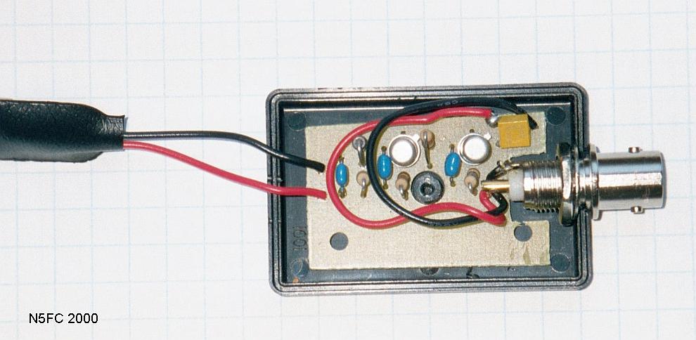 View, Cover Removed
I drilled a hole exactly in the center of the printed circuit board, just big enough to slide over the plastic standoff inside the key-chain box. In doing so, I think I cut one trace, which I re-routed using a piece of wire-wrap wire. I also used a nibbler on the output end of the board, to accommodate the NBNC jack's tail end, and tack-soldered the wires to the output traces on the PC board. When done, I screwed the cover on (one screw), and it ended up looking like this:
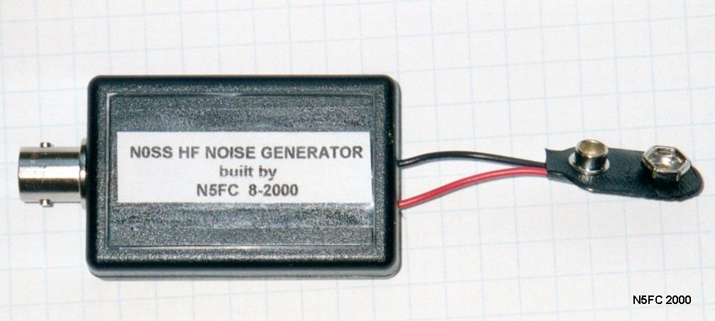 View, Cover Installed
Snazzy, heh?
Alternative Packaging (or, What About My Altoids Compulsion?)
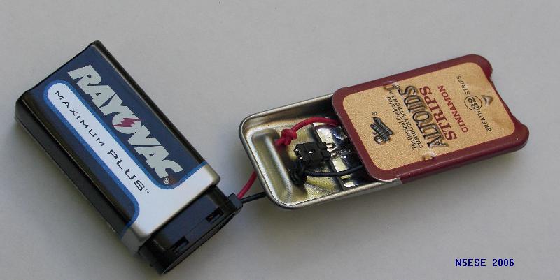
The packaging above was quite nice, but I wasn't happy until I could enclose both the battery and noise circuitry - and what better way to accomplish that, than in an Altoids tin? We'll show two different Altoids packaging schemes, beginning with the traditional (the N0SS noise gen), shown below, which needs no particular explanation:
 repackaged in Altoids tin
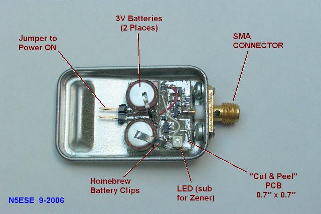
Super Teensey Weensey Altoids Packaging
This may be the worlds smallest noise generator project - I'll make that outrageous claim, and hope someone will surpass it, which I'd really like to see ;-)
Have you ever been standing by the cashier's counter at the drug store, waiting in line, and noticed a teeney-weeney Altoids box, for holding breath-mint strips, about an inch wide and less than a quarter-inch thick? Well, a friend of mine did, bought it, and challenged me to build something in it. I didn't want to do something as simplistic as an LED flashlight (which is still a good project); I wanted to do something truly electronic, and have it completely self-contained (which meant, batteries included). A noise generator seemed like a good candidate. I went with the following schematic:
Note that in place of a zener diode for noise generation, we substituted an LED. We still got plenty of broadband noise, but even with the same supply voltage, the output level was about 6 dB lower than with the N0SS circuit.
To pull off this packaging challenge, we needed two things: surface mount components, and very small batteries. For the batteries, we selected the Panasonic ML612S rechargeable 3-Volt MnLi coin cell. At about 1/4-inch diameter and 1/20th inch thick, we could easily fit two inside. I wanted a battery holder and Keystone makes one (their p/n 2991), but the minimum order was too much, so I kludged together some homebrew battery holders using tiny strips of steel cut from an Altoids tin (what else?). It didn't work too well, and I wouldn't recommend it, but it worked HI HI. See below:
The pc board was built as I frequently build one-off surface mount boards: using the tried-and-true "cut-and-peel" technique, i.e., utilizing a hobby knife to remove unwanted copper and form islands.
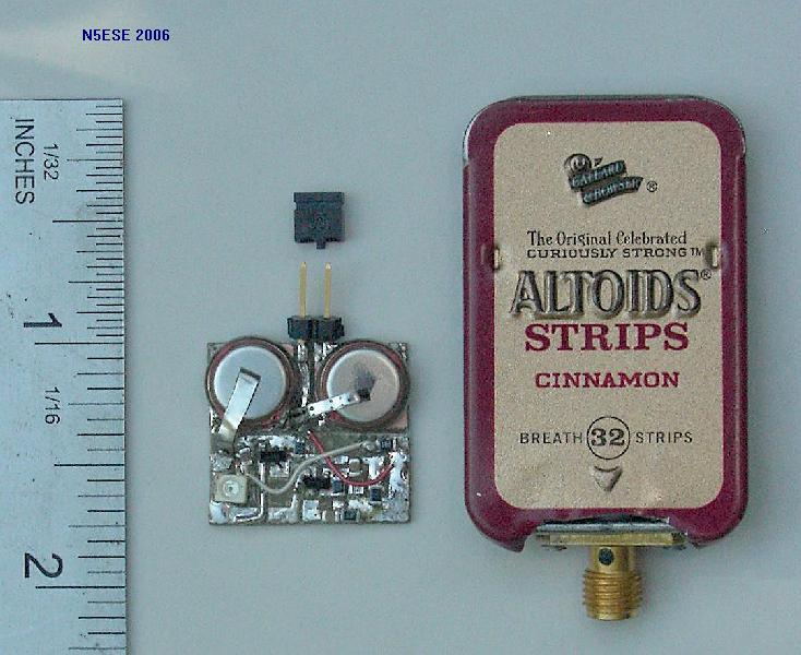
Yes, the completed assembly really did fit comfortably inside the teenset-weensey Altoids tin (total volume less than 1/4 cubic inch, and it really did work! Here's a picture, for scale:
The homebrew battery clips proved not to be reliable, and I guess I wasn't too surprised. So rather than risk an accidental short against the case, or intermittent operation, I finally reverted to an external 9-volt battery, as shown below:
All well, but now what do we do?
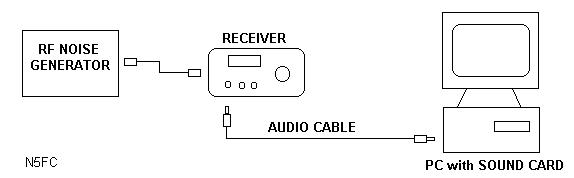
Well, we've managed to get the RF noise to the receiver, but now what? Did I mention Easy Street? There are a number of FFT software programs available, which use the PC's soundcard to sample the audio from your receiver, and provide a visual presentation of the spectral (frequency) content of that audio. For years, Richard Horne's Spectrogram software was provided free-of-charge, but now I see that it has a 10-day timeout, after which you must register for $50 (ouch!). While I haven't tried alternative programs, there are a couple that are still freeware: DL4YHF's Spectrum Lab, and I2PHD/IK2CZL's Spectran. Also, Spectrogram V5 may still be available -here- or -here- or -here-, but may not work with Windows XP.
When used with a broadband noise source (like ours, or the N0SS generator), these FFT software programs allow us to visually observe and measure the the frequency response of the aggregate circuitry (i.e., our receiver).
Spell it out for me...
Here's how it's done:
NOTE: The following procedure was written for the Spectrogram V5 software (running under Windows 95); if you're using something a little more up-to-date, you'll need to adapt, but the general procedure will be similar, if not the same.
OK... Real Measurements
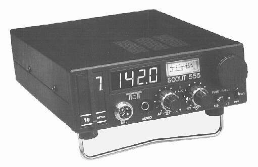
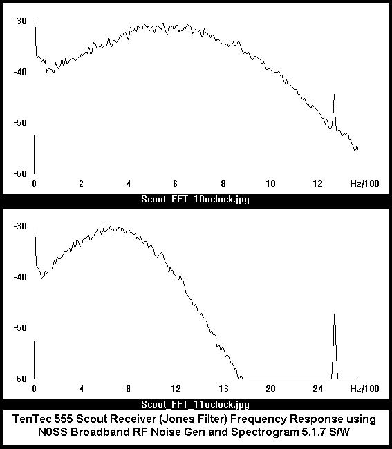
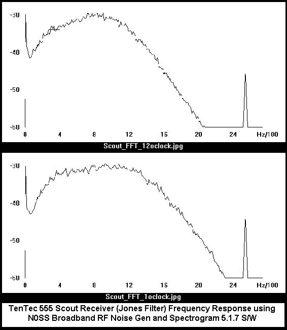
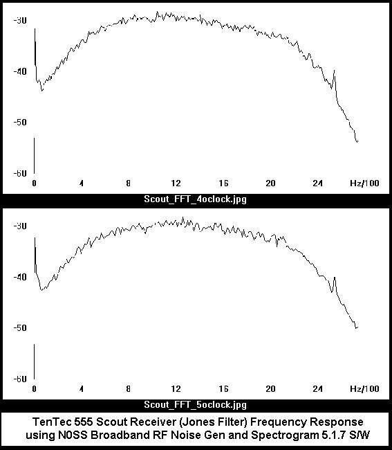
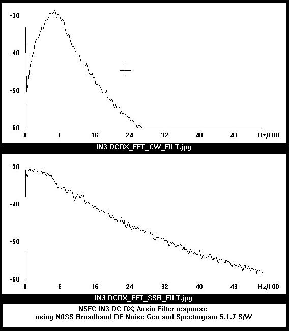
Here are some measurements I took from my own receivers. I was really curious about the response of my TenTec 555 Scout, which has a continuously variable XTAL filter (called a Jones filter, after the inventor and patent-holder). I wanted to know exactly what the filter response was at each position of the pot, in "clock" settings (all the way left being 7-o'clock, straight up being 12-o'clock, all the way right being 5-o'clock). I was also very curious about my IN3 DC-RX receiver (in the mini-Altoids box), which had a 2-position audio filter in it. Finally, I wanted to see the response on my TenTec 1340 QRP Kit, which has the cleanest filter I have ever heard in a cheap kit transceiver. Here we go:
Note: Each image is about 70 KB
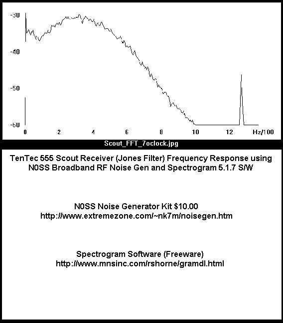
TenTec Scout, Filter response with control at 7-o'clock (all the way left)
TenTec Scout, Filter response with control at 8 && 9-o'clock
TenTec Scout, Filter response with control at 10 && 11-o'clock
TenTec Scout, Filter response with control at 12 && 1-o'clock
TenTec Scout, Filter response with control at 2 && 3-o'clock
TenTec Scout, Filter response with control at 4 && 5-o'clock (all the way right)
N5ESE's IN3 DC-RX, CW/SSB Filter response
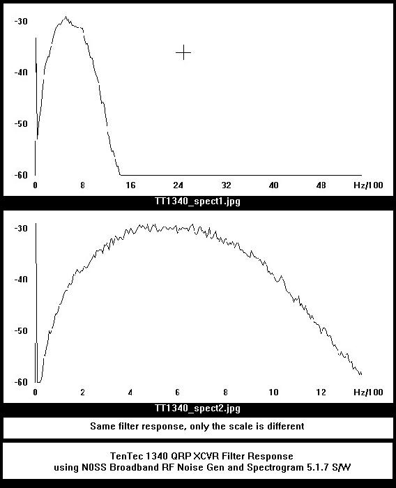
TenTec 1340 QRP Transeiver kit, Filter response
I learned a lot about my equipment. My TenTec Scout's low-frequency attenuation isn't very good. I sorta knew that, but I wasn't sure. I think my filter needs tweaking. Also, I could plainly see a "spur" at 1250 Hz intervals, which explains the little "whine" I hear when I have headphones on it. I'm not sure what's causing that. The Jones Filter, in general, works great, as you can see from the graphs.
On my IN3 DC-RX receiver, I learned that the SSB filter falls off a little too quickly, and is a tad narrow for SSB. I kinda like it that way, because I'm a CW op. But the narrow filter is "just-about-textbook" the way I designed it.
With the TenTec 1340 QRP Kit, it was easy to see what makes it such a good CW transceiver. The XTAL filter response is as clean as one could ever want.
![]() ...More Stuff Comin'...
...More Stuff Comin'...![]()
We'll add narratives here, on using the RF noise generator to do off-the-air antenna tuning, making antenna measurements using a simple bridge circuit, and troubleshooting receiver circuitry . That will have to wait until I get a little more time and ambition (wink). In the meantime, check the TenTec Amateur Products "TKIT" site for the TKIT-1051 Transmatch Tuning Bridge, which is an excellent (and cheap!) example of using an RF noise generator for antenna tuning. My version of the TKIT-1051 can be seen -here-, packaged in -- what else? -- an Altoids tin.
73,
Monty N5ESE
dit dididit dit