N5ESE's Version of the
NorCal Nor'Easter Shortwave Receiver
click on the picture to view larger image
| NOTE: 'N5FC' is my former call. This project was constructed while that call was valid, and you may observe references to it. |
Here, we describe my version of the NorCal Nor'Easter Shortwave Receiver Kit designed by Steve "Melt Solder" Weber, KD1JV, and kitted by the NorCal QRP Club. Besides being a unique and interesting design, we'll present errata and modifications for the kit, and a unique and compact way of packaging the project. Unfortunately for those who were snoozin', this was a limited edition kit, and is no longer available. Still, it is an interesting approach to a compact shortwave (broadcast) receiver, and is worth looking over.
The Noreaster is a surface-mount kit built on a board 3.3 x 2.1 inches, with parts mounted on both sides. Briefly, the kit is a shortwave broadcast (AM-only) receiver, of double-conversion superhet design, covering 5.2 to 17.0 MHz in 5 KHz steps. It is intended to run on a 9V battery, and use an antenna 3-4 foot antenna and headphones. Tuning is accomplished via three pushbuttons, is microprocessor controlled, and implements a phase-locked-loop synthesizer. Readout in KHz is provided on a single 7-segment LED display, which sequences through the current frequency on demand. In addition to six preprogrammed frequencies which allow you to quickly access the major SW-BC bands, ten user-programmable memories are provided. We won't go into any more detail about the design or operation, but you can access the schematic -here-, and the manual (including assembly, alignment, and theory of operation) -here-. The official errata can be accessed -here-.
I have some experience building surface-mount assemblies, so I'm not scared off by that methodology. In fact, I've come to prefer surface mount to through-hole assembly, because they go together more quickly. I've learned a few things along the way, to ensure success:
1) Get a pair of head-mounted magnifiers, X8 or better;
2) Use as little solder as possible;
3) Don't overheat.
Regarding the last two, I can't emphasize this enough: Don't oversolder, and don't overheat. Too much solder can mask a bad joint, and the thermal stresses of excess solder will tend to delaminate tiny chip capacitors, causing intermittent operation after some aging. Here's a clue: whatever you're thinking is enough solder, is probably way too much... really! To that end, use the smallest diameter solder you can get your hands on, 0.025 or 0.018" diameter, if you can find it. It will make your job of using minimal solder easier. While I hear many recommendations for the use of 2% silver-solder with surface-mount kits, I can assure you that very few commercial manufacturers use silver-bearing solder, and there is really no need to. You'll do just as well with 60/40 solder. Overheating tiny chip components is another cause of failed components, damaged boards, and bad solder joints. The solder should flow easily, and never smoke or boil. If it does, your soldering iron is too hot. If you have a temperature-controlled soldering iron, set it for 625 degrees F for all surface-mounted parts, and 675 degrees F for through-hole parts or parts with heatsink tabs. For the 1206-sized chips (12 = .12 inches x 06 = .06 inches) in this kit, a 1/16-inch soldering tip is fine. If you get excess solder on the chips or ICs, just remove the excess with a solder-sucker or solder braid, and you'll be in good shape.
The instructions are fairly clear, with a few caveats. For example, U4 is marked U6 on the board silkscreen, but it's obvious where it has to go. Be sure to consult the latest errata sheet to avoid making assembly errors. And do that BEFORE you begin assembly. The official errata sheet, at the designers web page, can be found -here-. Additional errata, in the form of an e-mail posting I made during my assembly, can be viewed -here-
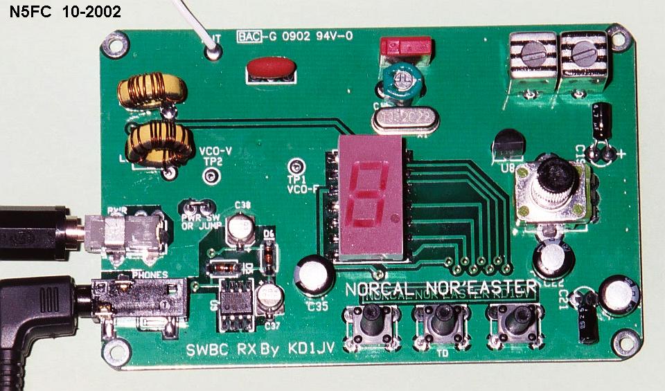
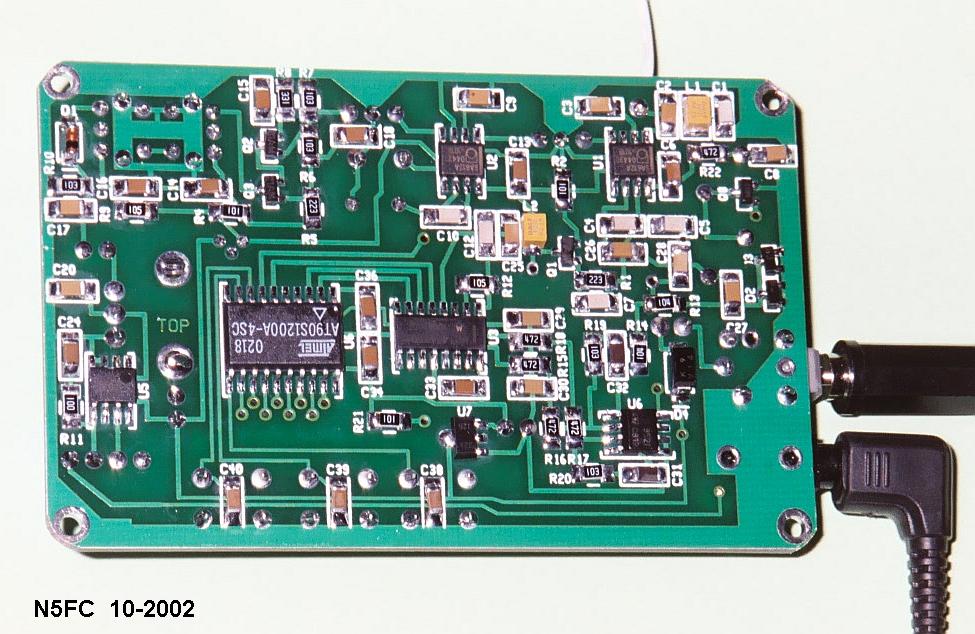
Here's a view of the "top" and "bottom" sides of the PCB, prior to packaging. Keep in mind, that what I call "top", the designer (and manual) call "bottom", and vice-versa. I call the side with the display and controls the "top", because they'll be facing me during operation.
For some time, I've wanted a shortwave receiver I could throw in my suitcase and not worry about losing, so I could listen to the world news on BBC while traveling. When NorCal offered the Nor'Easter kit for less than $50, I knew it was just what I was looking for. I wanted to package it in a way that would protect the receiver during transport, store necessary accessories, yet make it readily accessible and emminently convenient to use. As you've probably already surmised, I have a penchant for Altoids tins, and in fact was planning to package this in one, although it's a very tight fit and would mean the battery would have to dangle outside. While puzzling over how to accomplish this, my good friend Fred, K5QLF, presented me with the perfect solution: two Danneman Imperiale cigar tins (you know, the little skinny kind).

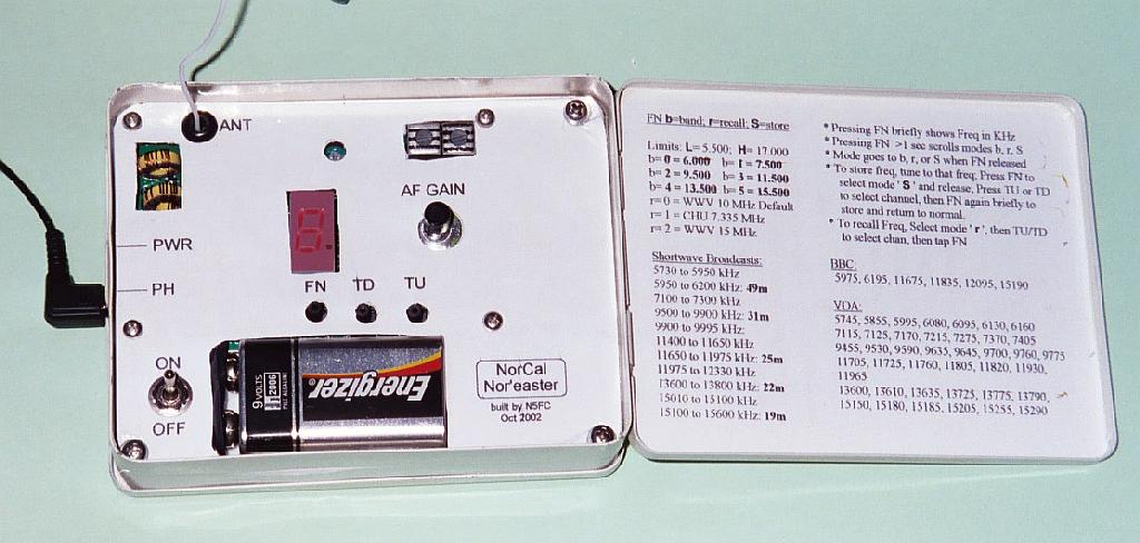
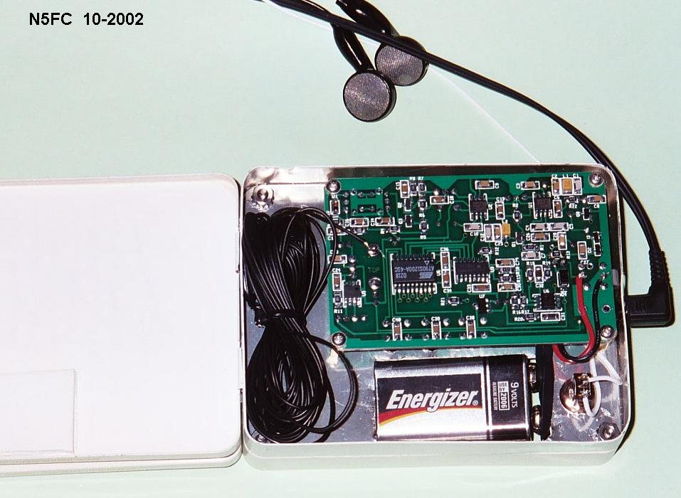
At approximately 4.4 x 3.4 x 1/2 inches, these tins have a hinged lid on them, but they are not thick enough to accommodate the Noreaster... that is, unless you stack them. And that's what I decided to do. In addition to enclosing the PCB and controls completely, there is room to store the antenna, counterpoise, and earphones, mount the 9V battery, and place a "cheat sheet" on receiver operation and broadcast frequencies. Stacked and closed, the entire assembly is 4.4 x 3.4 x 1" Thick. There is a top and bottom cover. The image at the very top of this page shows the unit from "top" view, with the top cover open. On the inside cover, you can see my cheat sheet, and on the left hand side, the interior of the top tin, with the display LED, AF Gain, and all tuning controls accessible. As you can see, the 4 foot wire antenna can be coiled and stored in this space, along with a set of earbud-type earphones.
Here's a closer view of the control panel:
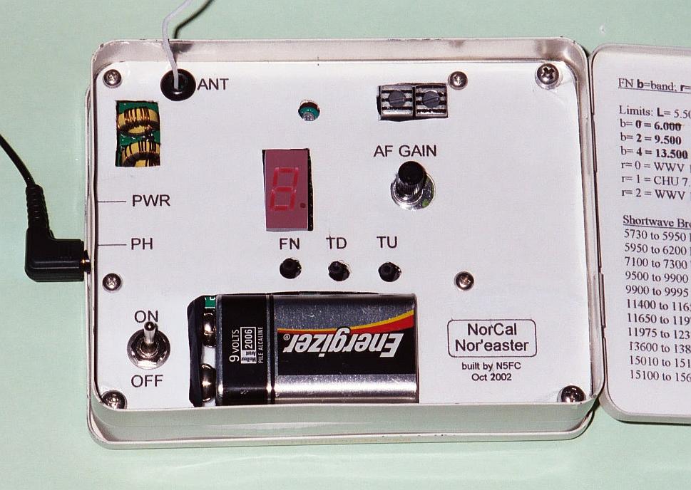
Look closely and you can see that the two tins were matched and screwed together. Using a step drill and sheet-metal hand-nibbler, holes were cut so that display and controls protruded into the cavity of the top tin, yet are completely enclosed without interference when the cover is closed. Obviously, the PCB is mounted in the bottom tin, on spacers of the appropriate length. Holes were also cut to allow the two toroid-wound coils to protrude, as well as the IF cans. This was purely a "fit" issue. Also, just above the display LED, a small round hole allows access to the trimmer cap, for oscillator trimming during initial adjustment. In addition, a square hole is cut for the 9V battery, which is just a smidgeon too thick to fit under the lid in one tin. A lable was printed on sticky-back paper (mailing lable sheets, available at any office supply store), and placed overall. Notice in particular the order of the three mode/tuning buttons, which were originally mislabled in thesupplied documentation. The image here is correct: FN = Function, TD = Tune-Downward, TU = Tune-Upward
For designing your own lables and/or making your own cuts, I've included my own measurements of the PCB -here-. Disclaimer: While these worked for me, and I was semi-careful in making the measurements, I don't guarantee there are no mistakes or typos in this document. Also, it may not print in true full-scale, so check carefully with a ruler before using it as a drill template.
Here's the view inside the bottom tin:
In the back side, you can see the power switch wiring, the PCB, and the counterpoise coiled at the left. My counterpoise is about 12 feet long. It's not required, but I think it helps reception somewhat.
The instructions in the official manual are fairly clear, and except for a mis-labelling of the three pushbutton switches on the drawing and on the silkscreen, all should go well. Remember, the switches (left-to-right) are: FN, TD, TU.
There is a statement on page 7 of the manual about the operation of the VCO, which may mislead you while troubleshooting. It states that "If the output of the loop amplifier, U6, pin 1, is at the positive supply rail, it means that it is trying to reduce the VCO frequency". In fact, if it is at the positive supply rail, it is trying to RAISE the VCO frequency, and if it is near zero volts, it is trying to REDUCE the VCO frequency.
If you didn't pay attention to the errrata, you'll probably encounter problems getting the VCO to act as described in the manual. In fact, you'll probably have a hard time tuning above 6 or 7 MHz. In the original manual, the descriptions of L3 and L4 are reversed. In fact, you should mount the larger (more turns) coil at L3, and the other at L4. This is actually reflected correctly on the schematic, but not in the instructions and parts list.
There's one other little bugaboo in the works... but it's only a minor inconvenience, and not a functional one. The microprocessor firmware, as delivered, displays the frequency as 10 KHz LOWER than the actual frequency selected. That is to say, if you want to tune to WWV at 10.000 MHz, the display will read 9.990 MHz. The designer, KD1JV, has indicated he is willing to reprogram the uP, for those that find this bug unsettling. See the KD1JV mail list for his e-mail address. I chose not to get my chip reprogrammed, because I can easily remember where to find WWV and CHU, and who cares about where the BC stations are, because they change frequencies all the time anyway ;-)
Operationally, the receiver is amazingly sensitive, considering the short antenna, and I am able to receive worldwide broadcasts day and night. Naturally, propagation conditions play a large part in what you'll hear, and you'll need to select an active band to find much activity. A little tuning around, and you'll soon know what to expect, when. Receiver current is about 35 mA, so many hours of listening can be had using a 9V alkaline battery.
73,
Monty N5ESE
dit dididit dit