WE6W Resonant Speaker (N5ESE Prototype)
built by Monty Northrup, N5ESE
(More pictures and diagrams follow the narratives)
built by Monty Northrup, N5ESE
(More pictures and diagrams follow the narratives)
| NOTE: 'N5FC' is my former call. This project was constructed while that call was valid, and you may observe references to it. |
On this page, we'll describe our prototype of the WE6W resonant speaker. I did not invent this device. In fact, I know very little about how it works. I recently ran across a description of it by the developer, Ed Loranger (WE6W). Click -here- for Ed's QRP-L post for this speaker, which contains the instructions I used for building this speaker. Ed tells me that an update design was finished but not yet generally available. I won't give his e-mail address here (at his request), but hopefully the information here will get you started.
I do not know enough about acoustics to offer any good formulas or explanations of why or how this thing works. You can check -here- for some basic formlas (sans acoustic theory). In brief, a resonant speaker is an acoustic filter with a speaker integrated into its structure. Signals applied to the speaker are reinforced and/or attenuated by the shape and volume of the device such that only certain "resonant" tones are produced efficiently. Ed's design here is one of the premier designs, because it provides a multi-order acoustic filter, with good stopband and steep sides. One version by KD7REM, much classier-looking than mine, can be seen -here-.
Ed tells me that the typical bandwidth is around 45 hertz, with resonances at the design frequency and odd-harmonics, and the stopband is at least 20 dB. I built three prototypes. All worked, all were useful, but all had some unexpected behaviors beyond what the designer described. The last version (Prototype 3) has narrower bandwidth and steeper sides than claimed by Ed.
A Request...
Ed has graciously allowed me to post his QRP-L description and a drawing of his concepts. An article in April 1983, QST provides more extensive background. An understanding of the design requires that you first read and study these carefully. Please don't ask me how to modify or amend it, or why yours works or doesn't work. I just won't know. Instead, post your results and questions to the QRP-L mail list.
If you really want to know how it works - without my bumbling experiments getting in the way of a thorough understanding - click -here-
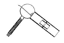
Here's a sketch of the original concept (we'll submit our version/prototype later):
The First Prototype
In my first attempt (which is 95% like the third and final version), I used a larger diameter inner tube (1.375 inch I.D. instead of the 1.1 inch specified by Ed). I also used a 1.375" O.D. speaker (instead of the specified 1"), thinking it was the cone diameter, and not the rim diameter that made the difference. While the speaker certainly worked, the local power-line hash caused serious ringing, and I was unable to attain the bandshape Ed claimed. Ed had stated that there were resonances at the design frequency and odd harmonics, but I had obvious peaks at all harmonics, although some were more prominent than others. I could not get a null at Fo + 100 Hz, but I was able to get a reasonable improvement by nulling the second harmonic. When I placed the inner tube/disc at halfway, I had a resonance at about 760 Hz, and adjusting the plunger to null the second harmonic, the plunger was about 1.5 inches recessed into the 6-inch tube. I asked Ed (via this e-mail message and this follow-up) for advice, and he responded with first this message, then this one. It appears I would need to use a 1-inch speaker (as specified by Ed), and shorten the inner tube to about 1.8 inches. I ordered the speaker (Kobitone Mylar/ Mouser 25RF006), but that would take some time to get. So I shortened the inner tube/disc combo to 1.75", and called it:
The Second Prototype
The version with the 1.75-inch inner-tube/disc, did not differ considerably from the first: It did not ring nearly as much as the first (with power-line hash), but it still had multiple peaks, with some at even harmonics. I took some measurements on this one, using a signal generator and a sound-level-meter on the bench. More questions to Ed regarding the multiple resonances brought this reply and this one. There was a lot of ambient noise in this setup, but I was able to create the following plot:
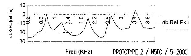
It was obvious I needed a little improvement, and the arrival of the 1-inch speaker from Mouser Electronics allowed better compliance with Ed's original design:
The Third Prototype
This is my current "as built". To test it, I took it to an acoustic anechoic chamber ("quiet room"), and used professional-grade measuring equipment. As a result, I am able to offer the following plots:
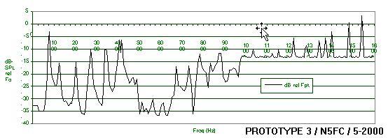
The first plot, from 200 Hz - 16 KHz, shows that the peaks (both even and odd) are all still there, but they are somewhat reduced from the first two prototypes. With the replacement of the speaker, the tuning plunger worked fine at Fo + 100 Hz (actually, I used Fo + 120 Hz).
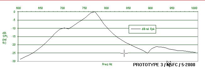
The second plot, an expansion of the first plot, focuses on the design frequency and its bandpass characteristics. As you can see from the plots, the speaker exceeds the designer's original claims, with 35 Hz 3-db bandwidth (as opposed to 45) and stopband more than -25dB down (at least near the design frequency). This version sounds great when used with a ham receiver, which already has a voice-bandwidth filter (and thus making the multiple higher resonances mute). Ringing is quite reduced from the first two prototypes, and the bandwidth is sharp enough to completely miss a weak signal unless you're dead-on (when all of a sudden, there it is!).
Construction Notes
Here, we'll offer details of construction of the third prototype. Mind you, the original designer (Ed, WE6W), informs me that the peaks occuring at 2 x Fo were unexpected, so there may be some construction anomalies in this prototype that contribute to that unexpected result. Still, in practice, the results are better than I expected.
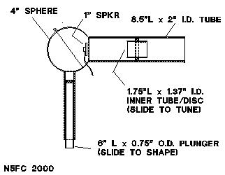
Refer to the following drawings for dimensions and construction notes.
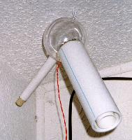
We found a clear plastic sphere kit in the local "Hobby Lobby" crafts store. It came in two snap-together halves, which (surprisingly) were pretty tight. It also had a little hanger-loop on one side. I think it was intended as a base for a homemade Christmas ornament. We used a hobby knife, the blade of which was heated over a gas stove, and cut the 2-inch hole carefully in one half of the sphere, and the 3/4-inch hole in the other half. The holes were located such that the two long tubes would be at 90-degree angles, and the entire assembly could be hung from the ceiling on a coffee-cup-hook, with the main port pointing at the operating position (as shown in the image at the very top of this web page).
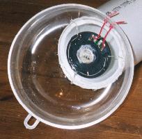
We brought the speaker wires out through two small (and tight) holes in the sphere. To mount the tiny 1.05-inch speaker, we heated three 1-inch pieces of AWG 20 bus-wire, then quickly placed them in the plastic rim of the speaker, sticking out like 3 spokes at 120-degree intervals. Then we epoxied them in place, being extremely careful not to epoxy the speaker (hi). When dry, we bent and cut the speaker-mount "spokes" carefully, such that the speaker would mount about 0.15-inch inboard of the two-inch hole in the shere half, centered on the hole, and firing straight out of the hole. After it was properly positioned, we epoxied it in place. The speaker picture shown below is similiar, but for a larger speaker (prototype 1, which was later updated).
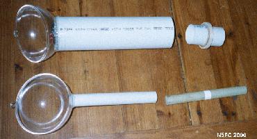
Then the 8.5-inch x 2-inch I.D. PVC tube was epoxied in place on the 2-inch hole (sand and clean mating surfaces first), using clear, quick-set epoxy. Then the 6-inch x 0.75-inch tube was likewise epoxied to the other sphere-half. The wood ring was carefully drawn onto 1/4-inch thick basswood (available from craft stores), then cut so that it would fit snug (fairly) inside the 2-inch PVC tube, and over the 1.75-inch x 1.375-inch I.D. inner tube. The wood ring (disc, as Ed calls it) was epoxied to the 1.75-inch tube, about midway along its length. Because we weren't getting a real good seal between the 8.5-inch tube's inner surface and the wood ring, we fabricated a rubber gasket (out of a flat sink stopper) to fit down onto the wood ring, and provide a seal and friction against the inside of the 8.5-inch tube. Concerning the 6" plunger, we used a piece of 3/4-inch O.D. fiberglas tube (Ed recommends metal), and we applied a ring of teflon plumbers' tape around the outside at a couple of points, to provide a seal and friction when the fiberglas tube was installed in the 6-inch x 3/4-inch I.D. PVC tube. Check the pictures below (especially the "parts" and "overall") to better visualize what was done.
Tuning was simple. Keep the volume/gain very low to begin with, because it's very easy to overdrive this speaker and create distortion products. The speaker is very efficient and doesn't need much energy to do it's job, but you might be tempted to overdrive it if you're "off-frequency" from the peak. If you're using a ham receiver as your audio generator, tune to a fairly strong CW signal. Use the broadest filter you have with the receiver. (2.5 - 3 KHz would be ideal). Starting with the 6-inch x 3/4-inch plunger nearly all the way out, and with the inner tube/disc at the midpoint (along the 8.5-inch tube), adjust the frequency (pitch) of the CW to peak (mine peaked at 750-780 Hz). Keep in mind, the tuning can be very sharp, and you can easily tune right past it (especially if you've never used a 35 Hz filter). Once you've found it, tune 100-150 Hz higher in pitch and adjust the 6-inch plunger slowly inward until you hear a "null" (for me, this occurred with the plunger approximately midway). That's it! If you want a lower or higher pitch for your filter, adjust the inner tube/disc inward (higher pitch) or outward (lower pitch) until you get the desired frequency. The Jones filter on my Ten-Tec Scout peaks about 670 Hz, so I later adjusted mine for that frequency, at which point the inner tube's outer edge was flush with the outer edge of the 8.5-inch tube.
Summary, and My Impressions
I had a ton-of-fun building and measuring and tweaking this speaker. One thing I found I need in practice is a switch to switch back-and-forth between the resonant and broad-band speakers. With heavy power-line hash (as I frequently have in my metropolitan setting), the ringing can be bad enough to annoy. Once, I thought I heard a weak CW station, only to discover that my ears were playing tricks on me as the noise rang in the speaker. Also, the tuning is very, very sharp, and your receiver's tuning resolution (tuning knob rate) better be up to the job. On a crowded band, when you do get a weak station tuned in, the resonant speaker can make it seem like you and the weak station are the only ones on the band. It's amazing. One annoying little quirk, when using QSK, is that your sidetone (transmit tone) may be pretty much eliminated, if it's not inside the narrow passband of the filter.
Our thanks to Ed Loranger, WE6W for his help in getting this project going. Again, for further information and learning resources, he suggests esoteric literature, April 1983 QST, and a review of patents. Also, submit reports and inquiries to the QRP-L mail list or the rec.radio.amateur.homebrew newsgroup.
73, and have fun! -- monty
73,
Monty N5ESE
dit dididit dit