Click on any picture to see a larger version
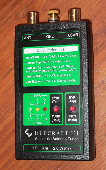
Elecraft T-1 ATU Kit
(Automatic Antenna Tuner)
This web page describes my experience with the Elecraft T1 Automatic Antenna Tuner (ATU) kit, which I built in April of 2005. The comments are based on a Rev A kit, with mods by myself and then further updated to comply with Rev A-1. As of the date of this writing, firmware version 1.07 is installed. Check the Elecraft Website to see if issues discussed herein have been cleared by further revisions.
Bottom Line Review - Up Front
Wow! I can't imagine anybody being unhappy with this kit! As usual, Elecraft has combined superb engineering with excellent ergonomics and performance. If you're a QRP portable or backpacking operator, this jobberdoo will make trying different antennas, or using that new multiband rig, an absolute joy! Go for it!
Construction
The kit arrived nicely packaged, and I nobly put it aside. I had family visiting in the house from the left coast. But later that day I would have about a four-hour window of opportunity where the girls were all going over to do girl-stuff at my daughter's house. No sooner were they out the door, and I wiped the peanut butter and blueberry slime off the kitchen table, and commandeered it for my assembly operations.
Elecraft provided two documents, which I thought was a bit odd. The first was an "Assembly Manual", and the second was an "Owner's Manual". The latter, at 12 pages, had a nice, full-scale color drawing of the finished ATU on the front page, and a schematic on the back page. Having the schematic in a separate document turned out to be useful during assembly, because you could double-check values and wiring as you went along.
They failed to provide a parts layout drawing and/or photograph, however, and that would have been useful during assembly. Frankly, though, between the instructions and the silkscreen on the pc boards, you really didn't need the layout to assemble it properly. However, it would have been nice after assembly, when I was double-checking some stuff, to have had it. Also, a layout drawing is really nice down the road, when you're trying to find a part for troubleshooting or repairs.
For the most part, assembly was very straightforward. There are a number of 0603-packaged surface-mount devices on the bottom of the board, but Elecraft has already soldered them in. The instructions don't say to do so, but I suggest you check them over carefully for good solder joints and missing components. My experience with manufacturing tells me that these types of components are the most likely to be missing or unsoldered, especially if they were wave-soldered or hand-assembled at the factory. A quick once-over with a magnifying glass will help to assure you won't be running into problems during checkout.
To Elecraft: thank-you, thank-you, thank-you for putting clear photos of each and every transformer and inductor in the assembly! There are two transformers and 7 toroidal inductors to wind. I've always felt a little apprehensive building toroidal inductors where the instructions say "wind 5 turns over 85% of the core". Sheesh, that's hard to visualize; 85% to me might mean something different to somebody else. But this time I had a picture and could wind my inductor to look exactly like theirs. Having the photos also will help folks new to winding toroids, to assure they wind them in the needed direction, and count the turns correctly. Just make 'em look exactly like the photos, and your worries are over!
There are two pc board assemblies: the main board and the itty-bitty control board. The control board will be a daughter board to the main board. The manual would have you assemble the main board completely, including wound inductors, and then assemble the control board. I chose to assemble the main board - all except the inductors - then the control board, and get the bulk of the soldering done and the boards cleaned up. Then I wound the inductors, and mounted them on the main board.
There's one tricky spot in the assembly, and it's obvious that it's tricky when you come to it. On page 14, you mount some connectors to the main and daughter boards, which enable them to be stacked at the proper height. In spite of some very nicely written instructions, and in spite of a photograph to guide me, I still managed to mount the board-stacking headers the wrong way, and had to disassemble them to get it right. Fortunately, I had only soldered one pin on each header P1 and P2, when I discovered the "fit" wasn't right. I managed to extract them without damage, and correct my error, but that one pin was then tinned instead of gold-plated - sheesh! What threw me off was experience (you see, experience sometimes is a hindrance). Elecraft was trying to tell me to mount P1 and P2 headers "upside-down" (long pins into the main board), but my experience was insisting on putting them in "the right way". I can see others doing the same. The photo is clear, but a few extra minutes of studying it would have prevented the problem I made for myself.
There is one goofy thing in the Owner's manual that can be a bit confusing, especially when you're installing the battery. If you look at the drawing on page 4, Figure 1, you might think you're looking into the battery compartment, and that the battery is backwards. In fact, the view shown is looking through the front cover (as if it were transparent), which explains why the battery looks that way. This led to some confusion on my part on which way the battery installed, and I had to trace back to make sure I got it right electrically. I also placed a sticker I made myself into the battery compartment, with a + and - on it, so I was sure which way the battery went. The Elecraft engineers were savvy enough to put a protection diode in the circuit, however, so no need to worry that you'll generate smoke if you accidently put the battery in wrong... it just won't work. However, the sticker is handly.
One nice thing about the battery compartment along those lines, which Elecraft points out in their manual. For transporting, you can flip the battery over in its compartment, such that it's still stored there, but it's no longer connected. This is very handy.
I had the entire kit completely together within my 4-hour window, and all the lights blinked and relays clicked, but field testing would have to wait until another day. Allow yourself about twice that if you're a beginning kit-builder.
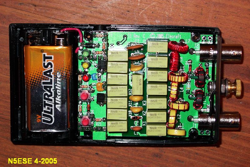
Here's a picture of the completed assembly, before mounting the front panel:
I did run into one anomaly during the testing. There is a test mode where you can step through the inductors and capacitors manually. In this mode, each time you press the button, it advances from L1 to L2 to L3, etc. Once, while in that mode testing, I tried to advance from L4, and it locked up and wouldn't respond to any input, nor go into any other mode. To clear it, I removed the battery for several seconds, then reinstalled it, and all came up normally. Checked the battery voltage and it was good. Restarted the test, and all went well. Not sure what that was about...
Field Testing
Two more days passed before visitors returned home and I had an opportunity to field test the T1 ATU. I decided to use the Elecraft K2 as my RF source, because it had an internal battery, and could operate all bands 160 through 10 Meters.
We carried the equipment to McKinney Falls State Park, one of my favorite places for portable QRP ops, and set up on a picnic table surrounded by 50 ft elms. I grabbed what I thought was the 85 ft wire, and slung it up in the form of an inverted "L", about 25 ft high. Then I laid out (on the ground) my typical radial package, which serves as my counterpoise: two 31 ft wires, two 25 ft wires, and two 16 ft wires, all connected to a common 30-inch wire . The antenna and counterpoise then connected to the T1 ATU via a BNC-to binding post adapter, and a 12-inch pice of RG-58 connected the T1 ATU to the K2 output jack. We put the K2's internal tuner in "CALP" mode, to bypass it, and we set the K2's power to 3 watts. We were set to test. First, you hold the "PWR/TUNE" pushbutton about 1 second, which causes the green LED to flash. At that point, you have about 3 seconds to provide RF, or else the T1 goes back into "sleep" mode to conserve battery. We started with 160M. I didn't have a straight key, just the paddle, so we usually tuned by sending dashes at about 10 wpm. The T1 tuned in about 2 seconds, and showed a 1:1 SWR. This is a short antenna on 160M, and I was pleased to see it tuned it up readily. The T1 has latching relays (15 of 'em, in fact), which hold their position when power is removed, which allows the T1 to "sleep" when not actively engaged in the tuning process, thus conserving batteries. By the way, the latching relays are expensive components, and probably account for about 1/3 to 1/2 the total cost of the unit (which was $135/kit).
Now is a good opportunity to point up two very nice features of the T1 ATU. First, you don't have to have a contiguous, uninterrupted CW signal to tune it; you can, but you don't have to. You can tune with dots and dashes, using the paddle. This has a another advantage, maybe not so obvious, in that it lowers the average power dissipated by the unmatched final stage of the transmitter during tune-up. Tune-up time is longer, of course, because the T1 only tunes when there is RF available, but it seems quite happy to accommodate this intermittent mode. Tune-up this way can triple the time it takes to tune, and sometimes we found it took up to 15 seconds to get a match. LED's on the front panel make it clear when tune-up is complete, by indicating the tuned SWR, and then turning off automatically.
Another neat feature worth mentioning is the T1's front panel "Information" capability. The Info modes are accessed without affecting the current tuner match. To access the Info mode, you first tap the PWR/TUNE pushbutton, and then hold the BYP/INFO button for 1 second. The yellow LED then begins to flash the information in sequence, in slow visual morse code, beginning with the last tuned SWR, then the battery voltage, and some more stuff I won't get into. So if you just finished tuning, and you want to know the actual SWR of the match, you enter Info mode and find out. The result is flashed at you as "S1R2" (for SWR 1.2:1) or "S2R3" (for SWR 2.3:1) or whatever it was. I thought it would be difficult to read visual morse - I think this is about 5 wpm - but it wasn't at all. I found myself looking at the flashing LED but "hearing" the morse in my head. Cool! Elecraft also claims you can hear the Info morse in the receiver (as a result of harmonics of the T1's microcontroller's clocking), and I spent some time searching for it in the K2 on several bands, and never found it. Being able to check the battery voltage using the info mode is also very handy. After several hours of testing and playing with the info mode, the battery reading had dropped from 8.9 (fresh battery) to 8.1 Volts (flashed on the LED as "V8R9" and "V8R1"). I haven't had it long enough to tell what the battery life will be in real field conditions, but I think I'll get one of the new 9V lithium batteries just to make sure it lasts a long, long time.
We continued with the field testing and found we were able to match our antenna on all bands except 40 Meters. This seemed strange, since my K1 with fewer taps in its ATU, would tune this antenna fine. We would discover later that the antenna I thought was 85 ft long was only 65 feet long. This meant it was a resonant 1/2 wave on 40 Meters, which explains why the T1 ATU didn't want to match it. 40 Meters aside, the worst match was 1.8:1 on 30 Meters; all others were 1.2 or lower. Good matches, all around.
According to Elecraft, the T1 ATU's three LED's can be used to roughly measure power according to their state. To enter this mode without affecting tuning, you tap the PWR/TUNE pushbutton. When you then transmit, one or two of the three LED's will light, and depending on that combo, you can read power. While I didn't run a test to quantify it, I consistently found that the LED's indicated more power than I had. As an example, with 3.2 watts output on 20 Meters, I would have expected the Yellow LED to light, indicating 3-5 watts. Instead I got either both the Yellow and Red LEDs (indicating 5-8 watts), or just the Red LED (indicating over 8 watts). Hmmm... a grain of salt... over the shoulder ;-)
While trying to tune and re-tune on our half-wave on 40 meters, we did run into another anomaly. Once, after retuning about 5 times unsuccessfully, it froze up, and would no longer respond to pushbuttons. For a moment, I thought I had damaged it. But as before (during testing), I removed the battery for several seconds, then reinstalled it, and all came up normally.
A Surprise in the Mail
A few days later, I went to pick up the mail and was surprised to find an errata sheet and a kit of 4 parts in a bubble mailer from Elecraft. This was apparently a revision kit, but the instruction sheet declared in bold lettering:
Great! I thought I was already done, and now I've got to tear it apart... After getting over my little huff (I was mainly offended that Elecraft didn't e-mail me before they sent it out), I set about to make the corrections.
The A-1 Revision and Some Mods of My Own
The new revision was designed to accomplish two things:
Neither of these was a surprise to me. In fact, during assembly I was a little surprised that the relatively small FT37-43 cores were being used in an application where high SWR might mean high voltage/turn ratios across the transformer winding. And I had already replaced the 1/4-watt 51-ohm resistors with 49.9-ohm 1/2-watt metal film resistors I felt could handle the heat better.
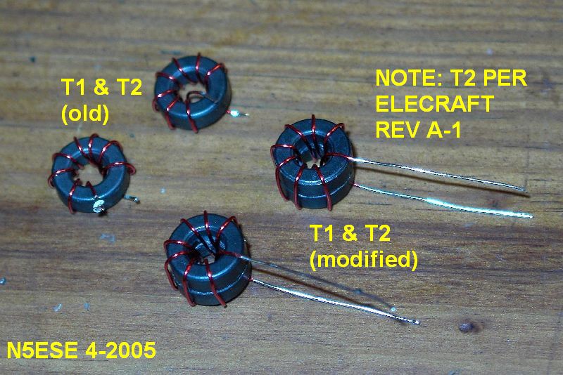
The method Elecraft wanted to use to beef up T2 was to use two stacked cores, instead of the one core. But they only wanted to do this to T2 (and not T1). The ATU uses a Stockton-bridge type circuit, which uses two independent transformers to effect an forward and reverse power sampling circuit. As long as the transformers act like ideal transformers, only the windings ratio matter, and I'm sure this was Elecraft's thought when they decided only to modify T2 (and not T1). But RF transformers rarely act only like ideal transformers, and if the two transformers are not constructed identically, then differences in leakage inductances and winding capacitances seem likely to cause imbalances leading to errors at the higher frequencies. For this reason, I grabbed some extra FT37-43 cores from the junk box, and wound both T1 and T2 in accordance with Elecraft's instructions for the new T2, super-gluing the stacked cores first, and eventaully replacing both T1 and T2 on the circuit board. Subsequent feedback from Wayne N6KR of Elecraft, assures that they fully tested the mod to T2 and found that it was unnecessary to do a like mod to T1. You can read Wayne's post -here-. Frankly, I'm surprised that balance was preserved at 6 Meters, but Elecraft has a reputation for diligent engineering and testing, and your trust in that would be well founded. Here's a picture of the transformers, as I built them, old and new:
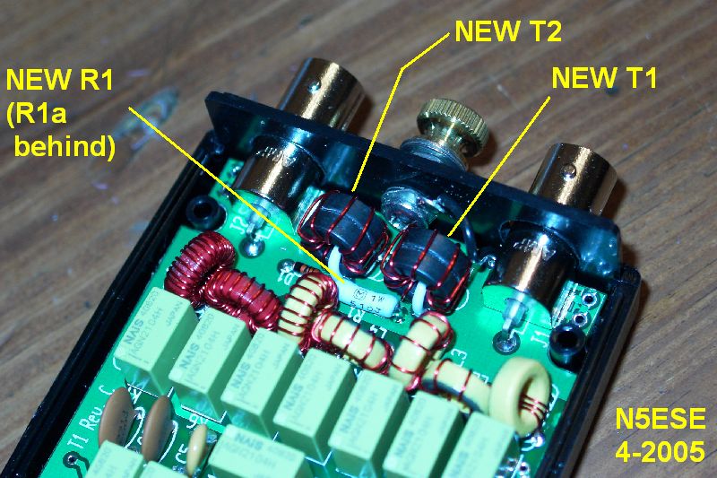
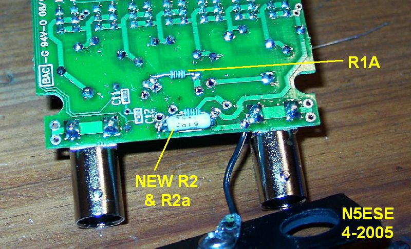
I like my bridge circuits to be 50-ohms, not 51. Mind you, the error is equivalent to matching to a 1.02:1 SWR rather than 1:1, but that's just the way I am about bridge circuits (type A - HI HI). Elecraft had provided two 51-ohm 5% MOX (metal-oxide) resistors to replace the original R1 and R2 bridge resistors. MOX resistors have good stable temperature coeefficients and good RF properties, so I was satisfied with that. I measured my resistors and found that they both measured 51.3 ohms. I calculated that a 2K resistor in parallel would bring them to almost exactly 50 ohms, so I pulled two 2.00K 1% metal film 1/8 watt resistors from the junk box. The pad spacing for R1 and R2 on the pc board was for 1/4-watt resistors, and it was a bit of a challenge to get the two 1-watt MOX resistors to fit, especially on the bottom of the board where R2 must be flat against the board to preclude fit or clearance problems to the enclosure. [Hopefully, Elecraft will revise the board in future versions to accommodate the larger resistor package]. I then tacked the 1/8-watt 2.00K resistors (called R1a and R2a in the pictures) in parallel with R1 and R2. See the details in the images below. R1's 2.00K resistor (R1a) is tacked on the bottom of the board, while R1 itself is on the top.
Naturally, the changes are a lot easier to implement during assembly than after the fact, and I grumbled a bit while I was disassembling my brand new ATU, but we got the changes installed, and checked the unit out to make sure everything operated as before.
Conclusions
Just for grins, I grabbed the K2 and slapped it down on the kitchen table (cringe... OK, I didn't really slap it down... I'm not that dumb...). I then hooked up the T1 ATU and for an antenna used a 3-foot clippy lead to the nearby aluminum window casing. I wasn't hearing much in the receiver, but I decided to try to load it up. The T1 ATU tuned it on all bands 20 thru 10 Meters, and 40 Meters to boot, to 1.2:1 SWR or lower. There wasn't much improvement in the receiver, and I didn't try to make contacts, but I was certainly very pleased with the tuning performance of the T1.
Later, we made another trip out to Mckinney Falls to test the ATU with its new mate, the AT-Sprint. For the past two years, we've used the NorCal BLT as the tuner with this rig. It's a champ, particularly considering the cost ($25) and the size, but it can sometimes be a squinty challenge to find the correct combo of settings to get a match using the BLT. I like to experiment with different antennas when I'm field portable, and finding a new tuner setting on the BLT can be time consuming and sometimes frustrating.
We were able to match using the T1 ATU with the KD1JV (original version) AT-Sprint on all 3 bands (40, 30, and 20 Meters), using the real 85 ft wire configured as an inverted L. 40 Meters was pretty much dead that day, but we had several hours of good QSOs on 30M and 20M, and tuning the antenna couldn't have been easier.
The T1 ATU will now be a permanent part of my QRP Field Kit... I'm just wondering now if I need another?
73,
Monty N5ESE
dit dididit dit