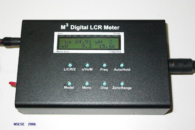
M-Cubed LCRZ Meter
(click on any picture to see larger version)
(click on any picture to see larger version)
Here's an exceptional piece of instrumentation for the serious electronics homebrewer, which you can build yourself. I've been homebrewing for over 40 years, and have many times wished I had a dependable and accurate way to measure hand-wound inductors, and to assess unknown components like poorly-marked resistors or inductors, or variable capacitors. In fact, I've built some fairly usable test equipment [see my L-Meter and C-Meter projects], and "gotten by", satisfied to get anywhere "in the ballpark".
Midway through 2006, the designers at M-Cubed Electronics invited me to participate in the beta-build of their LCRZ Meter. LCRZ stands for L (inductance) - C (capacitance) - R (resistance) and Z (impedance). As I write this, it is being officially unveiled on their web site, and I thought many of the prospective buyers might be looking for a "second opinion".
As with earlier kits I have purchased from M-Cubed, this kit reflects the efforts of an outstanding team of designers who understand the "gotchas" and "foibles" of test equipment, and have applied their exceptional expertise and knowledge to create a first-class instrument. There are a number of LCR meters on the market, and even some handheld DVMs (Digital Volt Meters) that claim to measure inductance and capacitance. None that I have encountered - at least anywhere in this price range - can approach the performance of this unit. Once again, the hardware and software designers at M-Cubed have provided us with a feature set is amazing, in a package that is easy to assemble and very well documented.
So, What Can It Do?
At work (I am an electronics professional), I have access to some pretty good laboratory-grade measuring equipment. One that I use frequently for checking inductors and capacitors is the Philips PM6303 LCR Meter (now made by Fluke). With it, I can measure virtually any inductor and capacitor to great precision, from devices intended for power and audio circuits, to those intended for VHF and UHF RF circuits. In addition to the basic parameters (Henrys and Farads), the lab instrument will also automatically compute and provide Impedance, Quality Factor, and Dissipation Factor. Pretty nice instrument, and you can own one (used) for between $500 and $900, depending on how savvy a shopper you are, and how patient ;-)
The M3 LCRZ Meter provides almost the same feature set and accuracy as the PM6303. The lead inductance/capacitance can be trimmed to zero, and the measurements are automatic (no null meters to zero, or pots to turn). In fact, the LCRZ may even be better in some respects (for one thing, it's about 1/20th the size!). While the LCRZ has a number of features I will never use, which you can read about in the manual, I find it most useful for measuring:
Yeah, But Are Those Really Good Numbers?
If you have one of the newer, fancier DVMs, you probably have a capacitance measuring function, and maybe even one for inductance. And if you've ever tried to measure a small capacitor or inductor (say, less than 100 pF, or less than 10 uH), you've no doubt discovered that the readings are not to be trusted. In fact, even at the mid-range (components for audio and power circuitry), the very best accuracy you can expect is probably in the neighborhood of +/-3 or +/-5 percent. And that's probably OK for most general purpose audio work, or for sorting mid-range components. But it's pretty much the square-root of frustration for any work done at HF radio frequencies, let alone VHF or UHF.
The LCRZ erases all those concerns. It is quite capable of accurately measuring down to, and/or resolving to a very small fraction of a pF or uH, and resistances into the milliohms. And all this with a basic stated instrument accuracy of +/-0.2% [yes, that's decimal two!]. The aforementioned PM6303 is rated at a somewhat looser 0.25%, so you can see what a bargain the LCRZ becomes, doing the same job or better for a whole lot less dinero.
NOTE: In their most recent documentation (see page 10 in the manual, available online), M-Cubed presents a chart for accuracy, based on test frequency and impedance measured. For most "mid-range" values when using test frequencies up to 10KHz, one can expect instrument accuracy of +/-0.2% or +/-0.3%. At the impedance extremes, and at higher frequencies, that accuracy spec is loosened to +/-0.8%. Again, see the chart and this will make more sense. The fact that they published a chart like this gives me a high degree of confidence in their technical ability to analyze and assess what their real-world accuracy is... and that's quite refreshing in a technical market where hype rules more often than reality.
Assembly - Hey, it's a KIT!
Let me say up front - I love building stuff. I've built lots and lots of kits, ranging from my first Heathkit in 1967 (an FM Radio, which my mother still uses), to the latest surface-mount technology. Aside from basic skills (soldering and patience), I've found that the biggest predictor of success with kit-building is the assembly documentation. M-Cubed documents are clear and easy to follow. And because they use a beta-proving process, most all documentation errors get worked out before the average builder even knows about the kit. So as long as you're reasonably literate, and have a modicum of skills and soldering experience, you'll have no problem at all building a successful assembly. Nonetheless, even experienced builders occasionally install a wrong component or make a bad soldering connection, and the folks at M-Cubed are amazingly good at zeroing in on the problems, should they arise.
From an engineering standpoint - and I've done a little in my time - a lot of hard work has gone into making the circuitry robust, so that each kit performs as expected, with no surprises. These guys know what they're doing. Software (actually firmware, because it's pre-programmed into a microcontroller chip), reflects attention to detail and a keen knowledge of human ergonomics. Having also done a little research on the methods used and the math behind them, I can confidently state that the M-Cubed approach is solidly grounded in electronics theory. In fact, I learned a thing or two just reading the manual. That background and experience makes possible a simple, small device that can be used almost automatically, with a minimum of operator intervention or knowledge required. And it also makes possible an advanced feature set, available via front panel software driven menus, that computes impedance as Z at angle theta, R + jX, G + B, and can directly measure transformer ratios and mutual inductance. Not bad, not bad at all ;-)
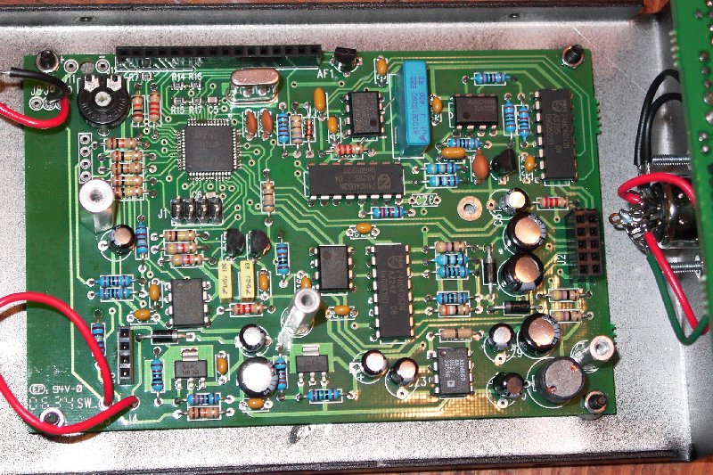
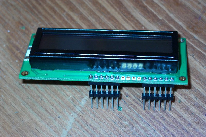
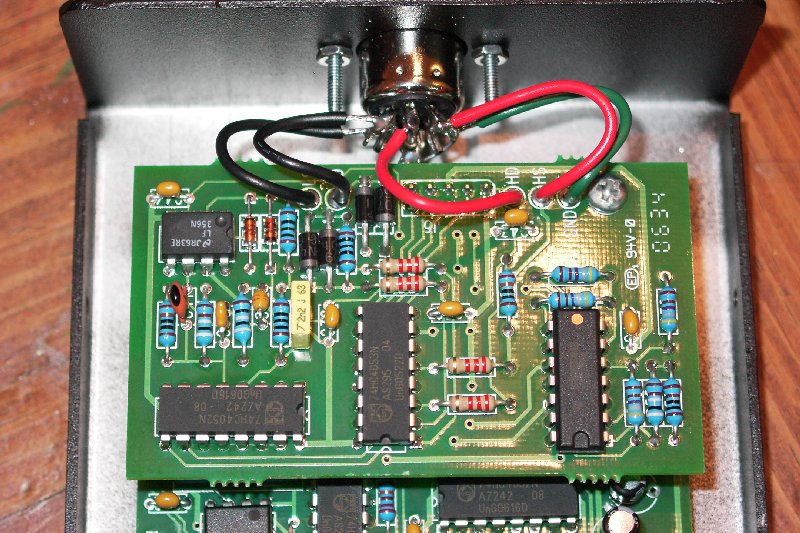
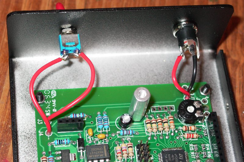
Assembly was straightforward, with a checkbox-type sequential assembly procedure, and some logical checks along the way. There are three PC Board assemblies, as can be seen in the image below:
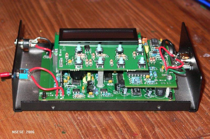
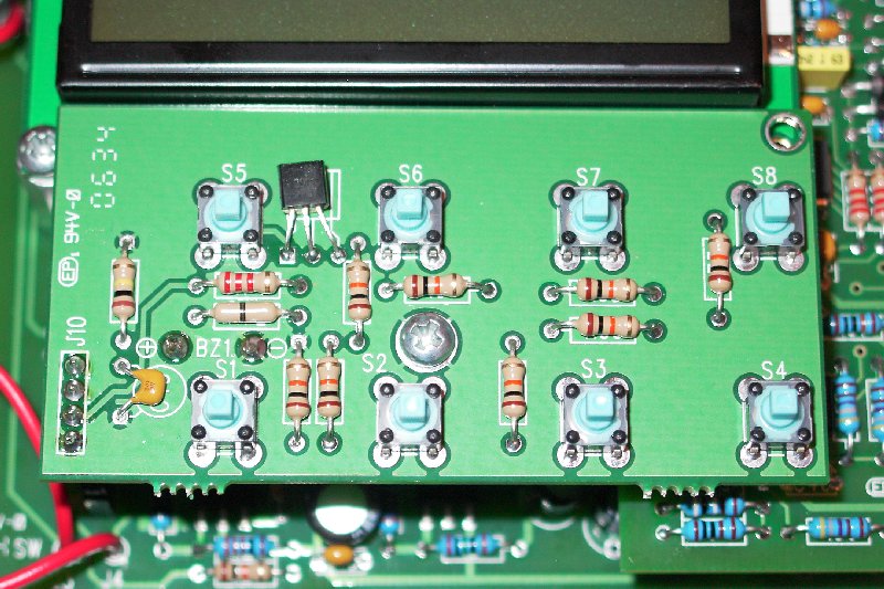
The large pcb at the bottom is the "Main" board, and contains the main microcontroller, A/D & Signal Generator circuitry, and power regulation circuitry. The two smaller boards plug onto the main board (i.e., daughter-boards). At the middle-right is the "Input" board, which hosts the signal conditioning circuitry and input interface. At the top is the "Keypad" board, which supports the eight pushbutton switches. Behind it is the the 2-Line (2 x 16 char) high-contrast LCD display, which also plugs into the main board. As you can see, there is minimal external wiring: the DC power input connector and power switch (at the left), and the input (measurement) connector at the right.
For those who are SM-phobes (i.e., surface mount scaredee cats), RELAX. M-Cubed pre-mounts all the surface mounted parts. Frankly, that takes some of the fun out of it, but there ya' go...
The assembly manual seemed very straightforward to me, and I finished the entire job in one long evening (about 8 hours). Wherever there was a chance for confusion, the M-Cubed team includes a picture. It would be hard to put this kit together wrong, but then I may not be the best judge, as I've been at this many moons. Beginners, be forewarned.
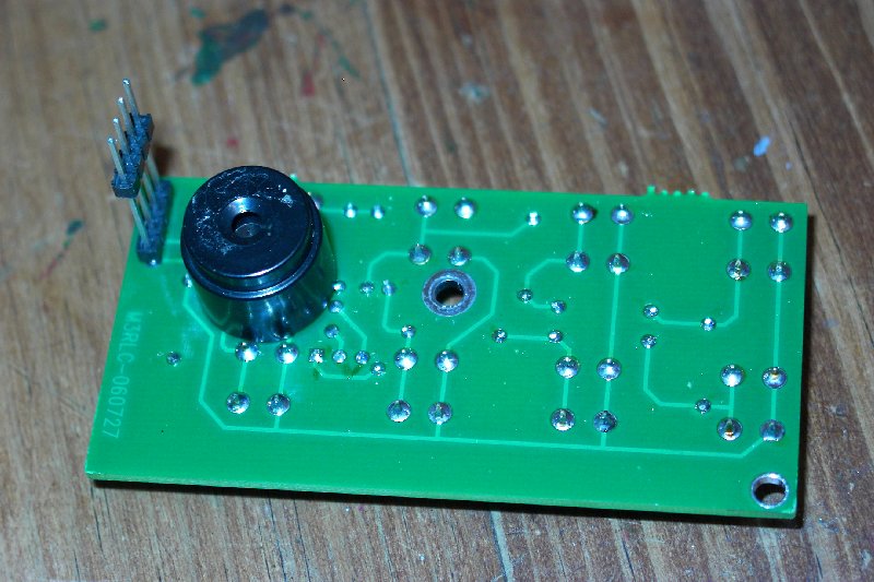
The trickiest and most time consuming part of the entire assembly may be the assembly of the input cable, pictured below:
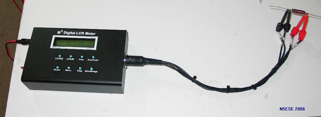
The input cable consists of a DIN connector with four equal-length (15-inch) lengths of RG-174 miniature coax, each terminated in a common hook-type test clippy. Now, if you've ever tried to solder to an RG-174 coax cable, you know how tricky that is. The successful completion of this assembly is important, because the accuracy of the measurement (especially at low values of inductance and capacitance) depends in large part on the balance and integrity of the cable assembly.
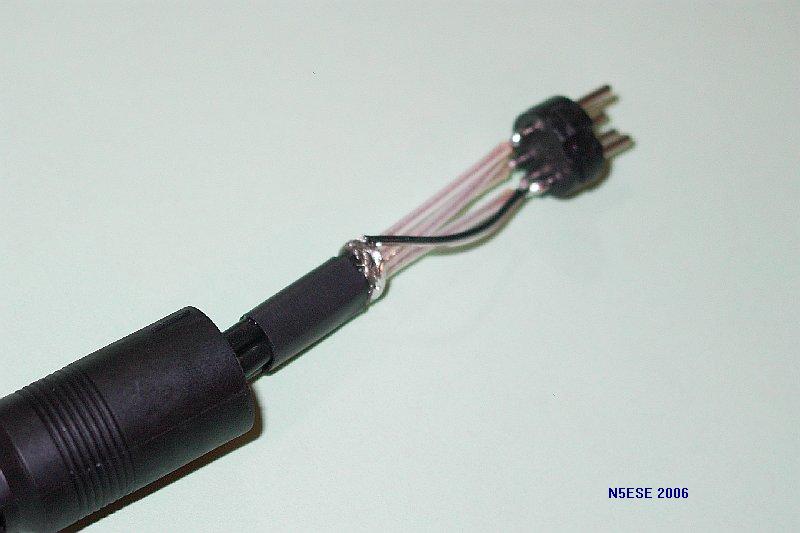
By the way, the 4-wire system of measurement is based on using two wires to "sense" the measurement point at "nominal load", and two wires to apply the source signal to the component under test. In the case of the M-Cubed LCRZ Meter, the source signal is a low distortion sinusoidal signal at one of ten frequencies between 100 Hz and 15.625 KHz. A probe built in this manner for 4-wire measurement is commonly known as a "Kelvin" probe. Commercial Kelvin Probes are fairly expensive (typically costing more than the entire LCRZ kit), so the efforts made in building this probe assembly carefully are well worth it. The instructions give you some checks to make during and after assembly, but I managed to short out one coax anyway, and had to re-trim all four to correct it. For me, the trickiest part was soldering a wire ring to the outer braid, to effect a common shield point for the probe wires. In doing so, I melted through the center conductor insulator on one of the wires. Below is a picture of that part of the assembly. Those who have tried to solder RG-174 braids will no doubt give a knowing nod.
M-Cubed has recently added two optional kelvin-type cable assemblies, at additional cost. Scroll down toward the end of the page for coverage on these newer cables. For more details about construction, scroll down to the bottom of the page, where there are another half-dozen or so links to pictures.
Calibration, Or, Can I Trust This Thing?
The final step in Assembly is "Calibration". Without calibration of some kind, even a hobbyist's instrument is "just guessing". This instrument won't be NIST-Traceable, but you can be reasonably confident after assembly and calibration, that it is operating within specs. As I said before, the crew at M-Cubed is pretty savvy, and damn clever besides, and has provided an effective, streamlined, and semi-automatic way to calibrate your instrument. In fact, it's so easy, I find myself doing it way more often than I need to.
A kit of six ultra-precision (0.1%) resistors is provided for calibration. BAG AND MARK THESE CLEARLY, AND SAVE THEM SOMEWHERE! To calibrate, you press a special sequence on the front panel pushbuttons, and enter calibration mode. From there, you're prompted to install each of the resistors in sequence. With the specified resistor mounted, you press the button, and sit back and watch. The LCRZ Meter executes an array of measurements at each of the source frequencies automagically, and stores the calibration correction values in non-volatile memory.
After that "periodic" calibration (once every six months or a year should do it), you're ready for routine measurement. The LCRZ is capable of automatically trimming out any probe and stray reactances, by performing a compensation test for "shorted" and "open" probe conditions. M-Cubed calls this "zeroing", and recommends it be accomplished each time the unit is turned on. The easiest way to do this is to push the front panel "Zero/Range" pushbutton, and then push "Open", followed by "Short" on the software menu. Each test will automatically cycle through each test frequency, storing compensation values for the "extremes" (open or short), and effectively "zeroing" the meter. Observations
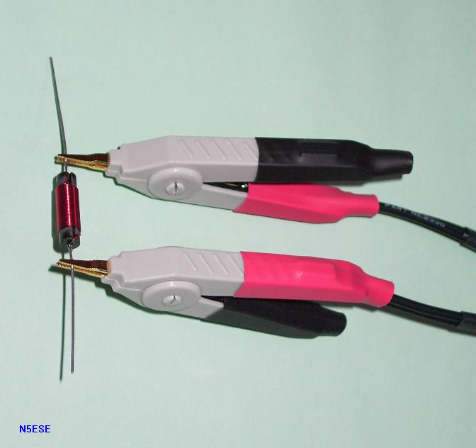
Making measurements is easy with the "as-built" kelvin probe assembly, and even more convenient with the optional assemblies (scroll down for more info). The test probe has four "clippies", two black, and two red. Grab your component to be tested, and clip the two black clips close together on one component lead, and the two red clips close together on the other lead. Here's a picture of the probe clips connected to an inductor:
Most of the time, the unit will detect the dominant paramenter (inductance, capacitance, or resistance), and display it automatically. Occasionally, you may have to tell the instrument what the component is, by pushing the 'L/C/R/Z' button, until the parameter comes up on the display. In actuality, the instrument does all the measurements all the time, but it can't always figure out what you want to see displayed. For example, suppose I had a 3-ohm wirewound resistor for use as an emitter ballast in an audio amplifier. Likely, the meter would automatically display R=3.00 ohms, but you might be interested in the inductance of the resistor. Press 'L/C/R/Z' until you get 'Ls' displayed. Voila! Or, suppose you have a 200 nanoHenry inductor. The meter might detect it as a 0.50 ohm resistor, and you might again press 'L/C/R/Z' to see the inductance L. Or again, suppose you are measuring a 100 microHenry choke, and want to see what the resistance is (for computation of Q at an RF frequency). The meter automatically detects that it is 100 uH, but you'll need to press 'L/C/R/Z' to see what the series resistance is. Easy, huh?
By the way, I have a number of precision components in my junk box. I spent hours testing these precision components in an attempt to "wring out the wrinkles" (is that possible?). I spent almost as much time making measurements as I did assembly. I have quite a few 1% and 2% capacitors in my "junkbox", which are my "standards". For some of the larger capacitors, I only have 5%, so that's a pretty sloppy standard HI HI.
I took a pretty good sampling of those capacitors, and made measurements, and tabulated them in a spreadsheet, which you can see -here-. In the first and second column, you'll see the expected (nominal) values, and in the remaining columns, you'll see the measurements. The majority of the capacitors measured within tolerance (as indicated by "Y" in the last column), and that gives me a pretty high degree of confidence in the LCR Meter. In fact, there were usually enough of them "in tolerance" that when one fell "out-of-tolerance", I was more suspicious of my stock than of the measurement. I suspect the batch of components I have (many of which came from surplus houses) actually has some fallouts, and the LCR Meter helped me find those. Hey - that's one reason I wanted it in the first place!
There seem to be a higher number of fallouts on the lower value capacitors, which happen to be rated precision capacitors that I really did expect to be in-tolerance. I did figure out how to zero the lead capacitance on those ranges, which got rid of about a half pF of error, but that still didn't bring the measurement to within the expected tolerances. The values seem to be biased to read LOW at the lowest values (like, 1.8 and 2.7 pF), and biased to read HIGH when measuring, for example, 8.2 pF. It could be one just can't get good measurements at those low values, or it could be my stock is contaminated. Because so much of these capacitors come from old surplus stock, I'm willing to concede the latter.
I also took measurements on inductors from my junkbox. Those results are tabulated -here-. I don't have any precision inductors, but I have quite a few commercial inductors with rated tolerances of 5 and 10%, so I measured a whole bunch of those, and reported a sampling. The attached PDF is arranged much the same as the capacitor tables. As a result, I'm a little concerned.
Nearly all of the 100 uH inductors read low, even though I had 5 different types that had known tolerances. In fact, looking at the results for both in-and-out-of-tolerance measurements, most seem to be reading lower than nominal. I'm wondering if there's a non-linearity creeping in there, or some other bias related to calibration or scaling or ranging?
Lastly, I also did a sampling of resistor measurements, and found that the measurements I made on the LCR Meter agreed almost exactly with my Fluke 77, from sub-ohms to megohms. The 1% resistors I sampled also measured well within tolerance.
Trying to test the accuracy of a measuring instrument by taking random selections from suspicious stock is certainly NOT a way to instill confidence, nor to assess the true usability of an instrument. A much better approach (but still flawed) would be to measure the same capacitors on a NIST-Traceable unit of comparable accuracy (like the PM6303, mentioned earlier), and compare the readings between the two instruments. Unfortunately, I just don't have the time to do this.
Overall, my gut feeling is that the measurements can be trusted, and that their accuracy could be as stated (+/-0.2%, or +/-0.3%), except possibly at very small values (sub pF or sub-100nH).
Also, be aware that there has been at least one software revision since I did these tests, and it is quite possible that any bug which contributed to an error during my testing, may have been fixed by now.
Limits - Why Are There Always Limits?
One of the limits of this device for RF work is that it cannot account for the non-linear effects of permeability vs frequency. This is because all tests are done at low (audio) frequencies. In fact, the highest test frequency available in the LCRZ Meter is 15.625 KHz. Therefore, a toroid-wound inductor that measures 2.5 uH at 15.625 KHz, but which is intended for use at, say, 7 MHz, may not actually have 2.5 uH of inductance at 7 MHz. An interesting test would be to wind two inductors, an air-wound inductor and a toroid, making both such that they read equal using the LCRZ. Then, measure the resonant frequency of an LC Oscillator using the same inductors. I believe that you will see a significant difference (5-10%) between the two. This is, in fact, one of the reasons I built my L-Meter, which uses HF oscillators for signal sources.
A related limitation is the Q measurement. In the LCRZ, the Q is computed from the Z and R measurements, based on the frequency of measurement. So when measuring a RF-type inductor, the R may be significantly higher proportion of the total impedance Z when measured at 15.625 KHz, than it would be if compared against the impedance it would have at the actual RF Frequency. This makes the 'Q' measurement pretty much useless for RF applications. Nonetheless, the resistance can be measured to milliOhms, and that value could be used to compute Q manually, computing Z at the frequency of interest (based on the inductance measurement), and using the measured Rs value. This would probably get you in the ballpark.
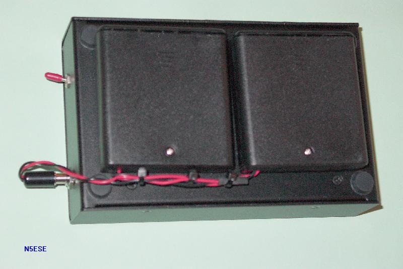
This is a small instrument, measuring roughly 6 x 4 x 1.5 inches. I was thrilled to see that there was enough room inside for a 9-Volt battery. But alas, the current consumption is over 200 mA, and a 9 Volt battery lasts about 5 minutes before it begins to sag (and get warm). And the 8.4V NiMh battery I tried wasn't much better. It is a royal pain in the patootie to have to find the wall wart and then find an outlet to plug in an instrument when you are trying to troubleshoot or sort parts for a project. Of course, you could leave it plugged in on the bench all the time, but for me the LCRZ is an "occasional" device that I simply won't be using daily.
My personal solution to achieve battery portability is ugly, but effective. I obtained two 4-pack battery holders (the kind that are fully enclosed, MPD p/n SBH-341AS), and wired them in series, to provide a nominal 12 Volts. I then connected them to a 5 x 2.1 mm barrel connector. I mounted the whole shebang on the back of the LCR, attached with Velcro (so I could change batteries readily). Here's a gander:
A couple of minor shortcomings with the probe assembly. First, the clippy arrangement works very well on parts with wire leads, but not so well with surface mount parts. In fact, it is darned near impossible to hold four clippies simultaneously to a surface mount chip HI HI. Some of my fellow beta test team members experimented with some clamp-arrangements for testing surface mount chips, and were quite clever and succesfull. I would also like to experiment with some fixtures for testing SM devices, but just haven't gotten "a round tuit".
NOTE: Since I wrote this, M3 has introduced some optional cable assemblies which overcome these issues; scroll down to the bottom to see a review of those new assemblies.
There's a small snafu with the DIN connector, which plugs into the LCRZ. In spite of a key and keyway, it is possible (no, it's EASY!) to plug the probe assembly in so that it's rotated to an "off-key" position. I thought my unit had gone bonkers, giving me weirdo readings (like negative inductance). Scratched my head til I was bald (really, then I asked for help from M-Cubed. Turns out they had encountered this too, and fired back a solution pronto. Boy, these guys are goOOod.
The cost may be off-putting to some hams and hobbyists. At $189 list, it's a lot to plunk down for an "occasional" instrument. But for those who are serious builders, I don't believe there's a better device on the market, at anywhere near this price. Oh - and I see M-Cubed has a "special", good through December of this year (2006), for $155, which takes a little of the initial "bite" out of it.
Conclusions
First, a disclaimer... while I have no financial interest in M-Cubed, I wouldn't classify myself as purely objective. I like kits, and I like innovative circuitry, and I like clever people. As a result, I am predisposed to seeing the M-Cubed products in a positive light. Nuff said?
The M-Cubed LCRZ Meter (or something very much like it) is a MUST-HAVE for serious builders and experimenters. I have had more fun with this than any piece of test equipment I've built in a long, long time (second only to my oscilloscope ;-)
73, and enjoy!
monty N5ESE
[scroll down further for additional info on kelvin cable options]
Construction Pictures:
The "as-built" input cable that comes with the M-Cubed LCR kit, as detailed above, does a fine job functionally, and is more than adequate for occasional use measuring leaded components. It gets a tad cumbersome when grading a large number of components (as, for example, trying to match a pair of capacitors for a filter, from among a pile of 5% types). It also falls considerably short for measuring surface-mount components (in fact, it's almost impossible).
M-Cubed now offers two optional accessory kits to address those issues. These are still kelvin-type input cables, and still plug into the meter using the same DIN connector, but the methods for connecting to the component are much more appropo to these situations. Here's a picture of all three input cables:
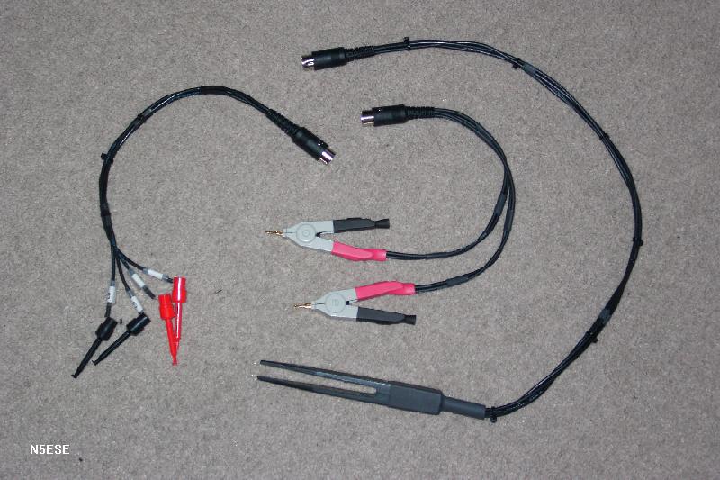
Leftmost, we see the standard "as-built" input cable, with 4 clippies. Rightmost, is the new surface-mount tweezer assembly. Center, see the new 2-clip style kelvin cable.
Construction is eerily similar to the construction of the original input cable. If you could build that one, you can build these.
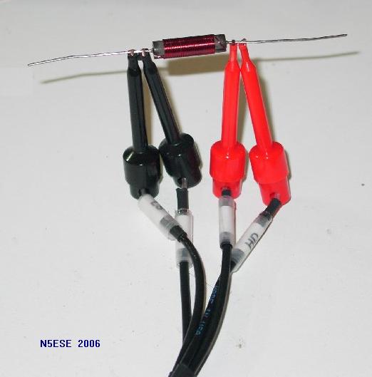
Here's a picture of the new 2-clip input cable, attached to an inductor:
With the addition of this cable to my lineup, the original cable has been relegated to "spares" status. It might, however, still be best suited for some components. For example, for a large inductor with lugs or screws, the original cable (with its hook leads) might make more sense.
Here's a picture of the new SMD Tweezer, measuring a 1206-sized chip resistor:
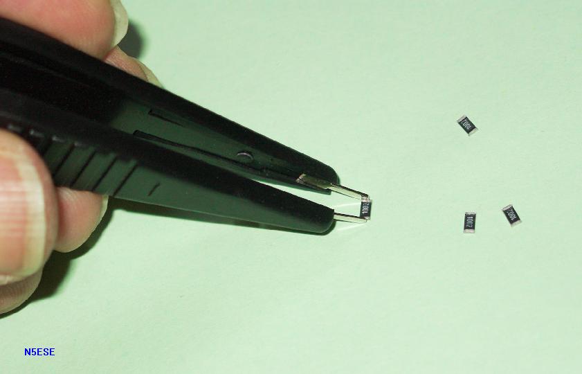
Of course, the very first component I tried to measure, projectiled across the room with a tiny "ping-click", never to be seen again. Thereafter, I was a little more careful in using the Tweezers, and managed to measure a dozen of so different components with no problem. I left the leads somewhat longer on the Tweezer, simply because of the ergonomics of holding the tweezer away from the work. The longer leads seem to result in more "noise" in the readings, as evidenced by a somewhat less stable display on some components (especially low value inductors and capacitors). Also, the tips appear to be nickel-plated (not gold plated, as on the other new cable), and that seemed to affect the ability to readily get a positive, low-ohmic connection. Those issues aside, and lacking other ready alternatives, I recommend these tweezers for their simple and effective utility with SMD components.
73,
Monty N5ESE
dit dididit dit