N5ESE's QRP Transmitting Inline Attenuator
(click on any picture to see larger version)
(click on any picture to see larger version)
| NOTE: 'N5ESE' is my former call. This project was constructed while that call was valid, and you may observe references to it. |
Any QRPer knows how much fun operating with low power can be. A decrease of power from 50 watts to 5 watts is -10 db, or about 2 S-units. The increase in fun is about an order of magnitude, too. Usually, decreasing power to a tenth of normal power can be effected simply by turning the transmitter's drive control down, if you have a commercial rig. But there's a point of diminishing returns, and it's frequently impossible to lower the power much less than a few watts, and even harder to know what that level is. With simple QRP rigs, the drive is often fixed, and the power thereby set to 2 - 5 watts. Wouldn't it be great to have the means to readily and easily decrease that QRP power by a factor of ten, thus making QRP even more fun? And for about 5 or 6 bucks?
Well, that's the basis for this project, a switchable 10dB transmitting inline attenuator. Simply place this device inline between your transmitter and antenna tuner (or other 50-ohm load). With the switch in the "BYPASS" position, full power goes to your antenna normally. A flip of the mini-toggle switch to "-10 db", and your output goes to one-tenth of its original power. In either position (assuming your antenna tuner is properly adjusted with high-power applied), your transmitter sees 50-ohms.
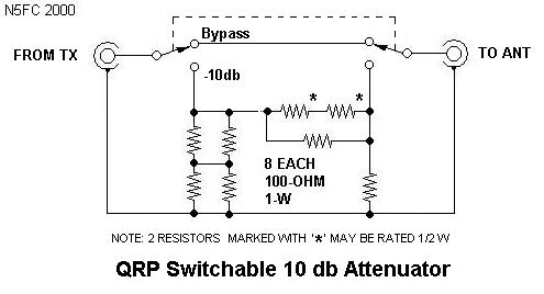
Below is a schematic of the switchable attenuator. We used 8 each 100-ohm 1-watt 5% metal-oxide resistors, available from Radio Shack for a mere 25-cents each (RS 271-152). The DPDT micro-toggle switch (RS 275-626, $3) was selected for it's small form factor and it's excellent ratings. Two UG-1094 BNC jacks provide my favorite means of connecting RF.
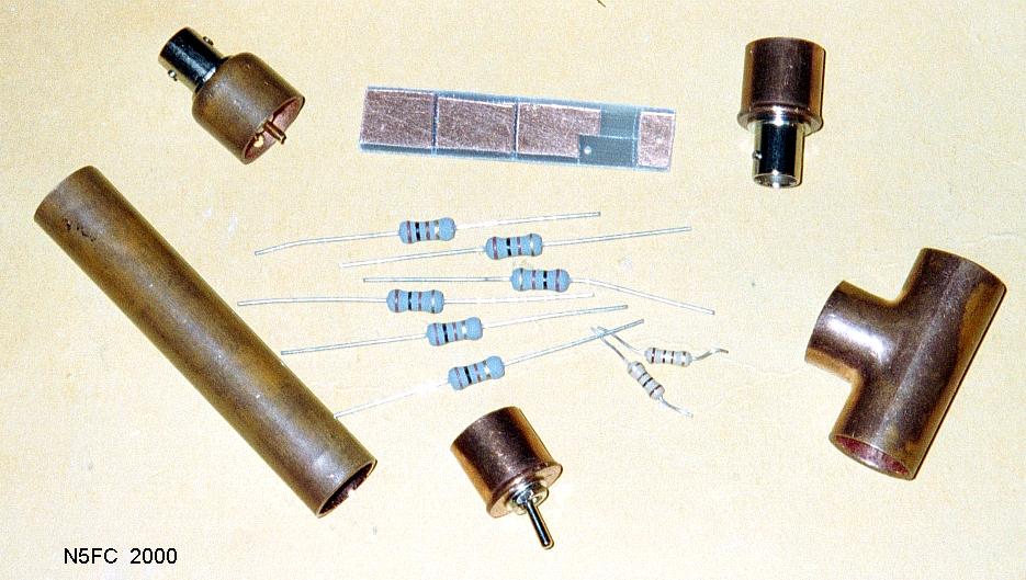
We're not talking a lot of parts... here's a picture of the parts gathered just prior to assembly:
If you do the math, you'll discover that the attenuator isn't really 10 db (it's 9.6). This means that for 5 watts input, you'll get about 550 mW out (rather than 500 mW). The compromise is miniscule, and allowed us to use equal-value, off-the-shelf resistors. The input/output impedance is still within 5% of 50-ohms, so it should provide low SWR operation throughout the HF range.
We mounted the resistors on a piece of scrap double-sided printed-circuit board, about 2.5 x 0.5 inches. Using a hobby knife (and SAFETY GLASSES!!!), we formed pads on both the top and bottom of the pc board. All resistors and wires were then tack-soldered to the pc board. Sorry, but you'll have to use teflon-coated wire for the wiring, because the resistors can get very hot in this application. Here's a sketch of the pc board copper and component layout:
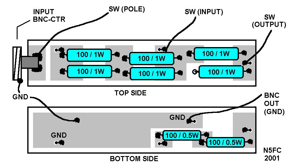
Note that where holes are drilled through the board, a wire provides continuity from top to bottom (solder on both sides)... otherwise, everything is soldered "surface-mount" style, with a big blob of solder holding the components down (don't get carried away). The center pin of the input BNC connector gets soldered directly to the foil where shown.
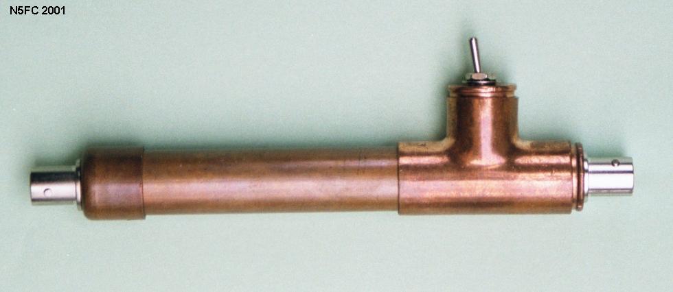
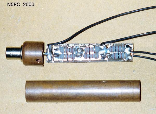
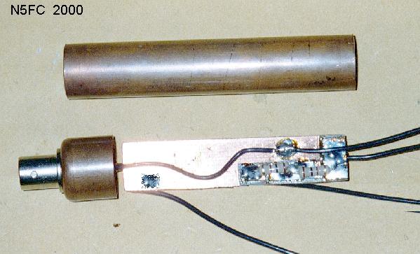
As you can see, I was still on my copper-pipe-kick when I built this attenuator. You may, of course, elect for some other packaging, though at 5-1/2" long, this unit is very compact and portable. The 1/2" copper pipe provides a convenient, compact form factor, is an excellent shield, and helps to dissipate heat to the outside world. Copper end-caps, available at most any hardware or plumbing supplier, provide a means of mounting the two UG-1094 BNC jacks and toggle switch, and closing the unit.
Here's a picture of the front and back-side board assembly just prior to putting it inside the copper tube:
Wrap the entire pc board assembly in plumber's teflon tape before installing it in the copper pipe, to prevent shorts. DONT be tempted to use any other kind of tape (because of the spot temperatures involved)
Check you wiring before applying power to this attenuator. Check that the "BYPASS" position shows 0-ohms continuity from input center-pin to output center-pin, and no continuity from center-pin to ground. Then, with the switch in the "-10 db" position, verify 60-65 ohms at the input (center-pin-to-shell) and the same at the output. Then, measure from input-center-pin to output-center-pin and verify 50 ohms (approximate).
How does it work?
I checked the input SWR in both the "Bypass" and "-10 db" switch positions. At 30 MHz and below, SWR was 1.1:1 or less. At 146 MHz, it was 1.3:1 in "bypass", and 1.6:1 at "-10 db". Attenuation on all HF bands was measured at 9.6 to 9.65 db. (Attenuation on 2 meters was not measured)
I keyed-down at 5-watts input for 60 seconds. The unit barely got warm. Still, I recommend keeping the input power to 4-watts or less for continuous periods of 30-seconds or more, and not more than 8-watts at 50% duty-cycle (like with CW)
The fun really starts when you put this thing on the air. As soon as I got it buttoned up, I started cruising 40 meters around the QRP calling frequency for a CQ. I didn't have to wait long before I heard Lionel K6CEQ, and gave him a call with the attenuator "IN", i.e., 1/2-watt output. He came back to me with his QRP 5-watts and a 559 report. We made a couple of solid exchanges at that power level, at which point I switched to "Bypass", gained a couple of S-units, and finished out our ragchew. Austin, TX to San Diego, about 1155 miles, and about 2300 miles-per-watt. Not Bad!
When the band is really hot, and I'm using the TenTec Century 21 (which allows you to adjust the drive level), I adjust it for 5 watts out with the attenuator bypassed. Then, I switch in the 10 db attenuator, and note the exact position of the forward power needle on my SWR Meter. Next, with the attenuator bypassed, I readjust the drive level to match that mark (i.e., 0.5 watts instead of 5 watts). Now, with the attenuator "IN", I'm transmitting 50 milliwatts, and with the attenuator in "bypass", 500 mW. Using this technique, I was able to call and exchange info with Jim, AL7FS, in Achorage, Alaska, using only 50 mW of power, a path of 3144 miles for 62,880 miles-per-watt!
For those worried about the attenuator being inline during receive, I have not found this to be a problem, as my TenTec Scout has plenty of reserve gain for the bands I work. On the DX bands, you may elect to switch to bypass during receive cycles.
Here's an idea: build two of these and work super-QRP!
73,
Monty N5ESE
dit dididit dit