N5ESE's Development Testbeds For AVR ATtiny84 & ATtiny85 (2023)
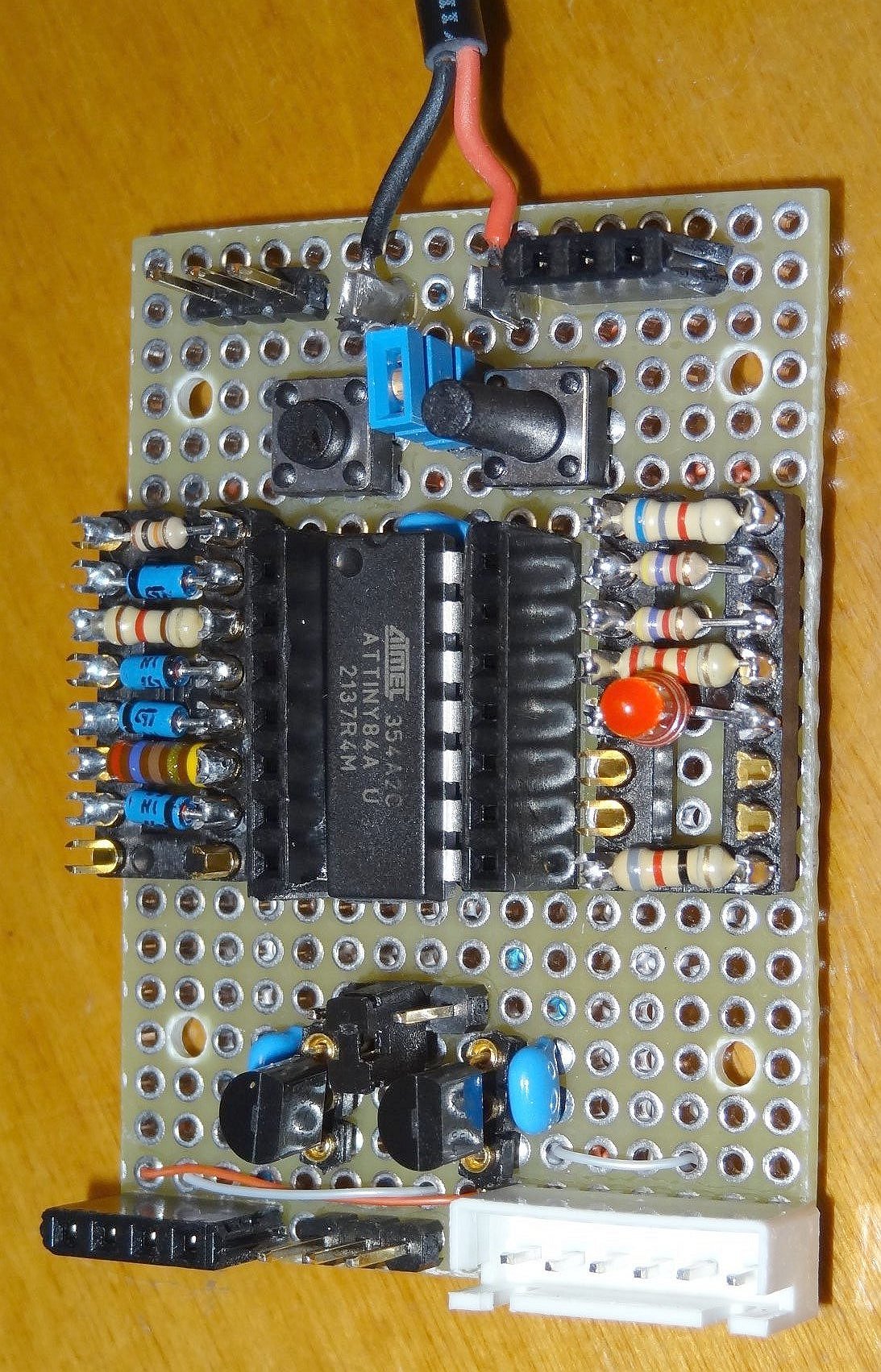
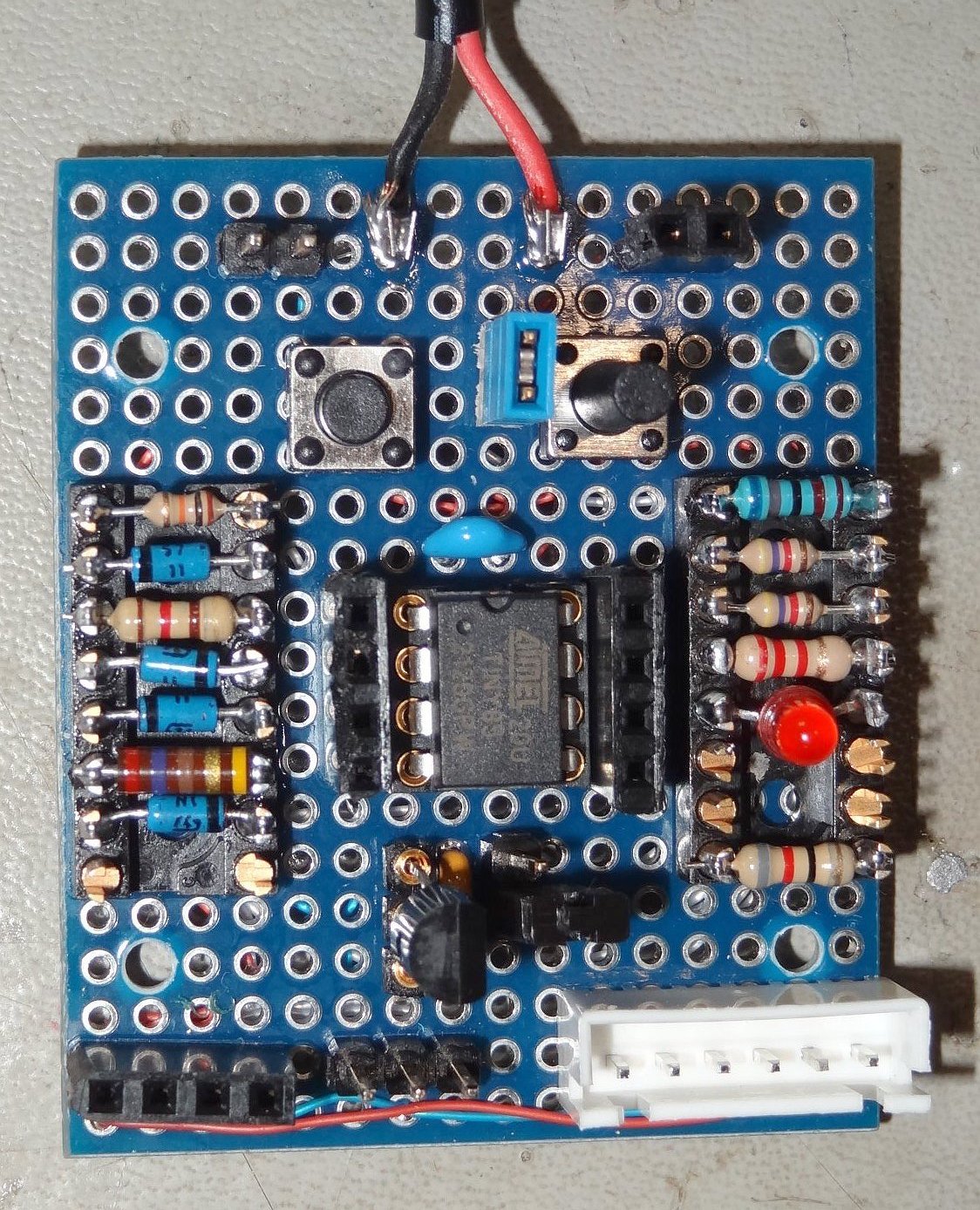
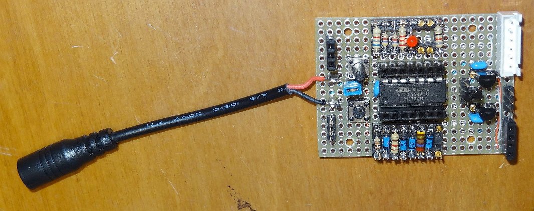 ...ATtiny84 Testbed
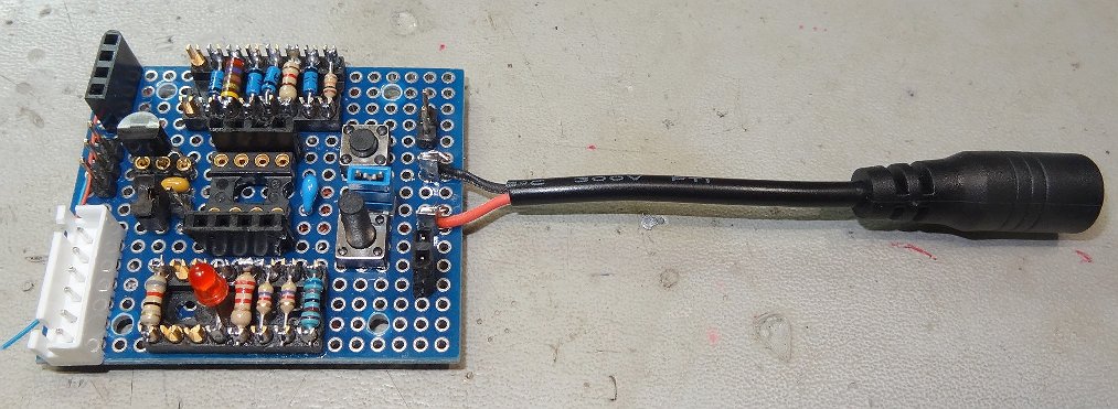 ...ATtiny85 Testbed
(click on either picture above to see larger version)
I really liked the little AVR ATtiny series of MCUs. The ATtiny84 is a 14-pin package (DIP or SO) and
ATtiny85 is an 8-pin package. Code can be written under the Arduino IDE, and uploaded using the
Sparkfun 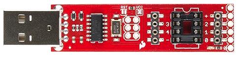 Tiny AVR Programmer.
These MCU's are NOT high-powered microcontrollers - they're 8-bit devices - but they have lots of useful
I/O, including 10-bit ADCs with internal reference and UART/I2C/SPI (serial comms)
capability, and they clock pretty fast - up to 20 MHz - and they don't actually need a clock. Oh,
did I mention they're CHEAP? Like under $2 !! They're very power stingy, and fit the bill for any
number of small-scale ham radio projects. Often, developing these is faster, easier, and more compact
than trying to replicate the function in hardware. Example: my simple voltage monitor
using an 8-pin ATtiny85.
After fooling with these for a few weeks, I realized I needed a small universal testbed for each
version (8-pin or 14-pin), so I wouldn't have to reinvent the wheel each time I had a new idea, and
with the following common functionality:
    - onboard reset pushbutton
    - onboard user-input pushbutton
    - external voltage reference (onboard)
    - connections for Serial I/O (TTL serial comms)
    - connections for I2C I/O (for Display or ??)
    - ISP Programming capability (using the Tiny AVR Programmer, mentioned above)
    - Test Socket on every MCU pin (for probing or jumpering to other components)
Schematics
The schematics are very similar (just slight variations). If you've ever programmed a microcontroller
of any flavor, you'll see what I'm trying to do here.
...Schematic, ATtiny84 (14-pin MCU)
...Schematic, ATtiny85 (8-pin MCU)
Construction
While it would be nice to have a printed circuit version of this, it would also then be "chiseled in stone".
My method of choice here was perf board - the kind with plated-through holes on 0.1-inch pitch.
General layout and component identification is included on the schematic. I use point-to-point wiring
using a small soldering iron. It's tedious and painstaking, but it can be done, and it's
durable enough for my use. Below are pictures of both versions, first the 14-pin testbed, then the 8-pin:
 ...ATtiny84 Testbed...
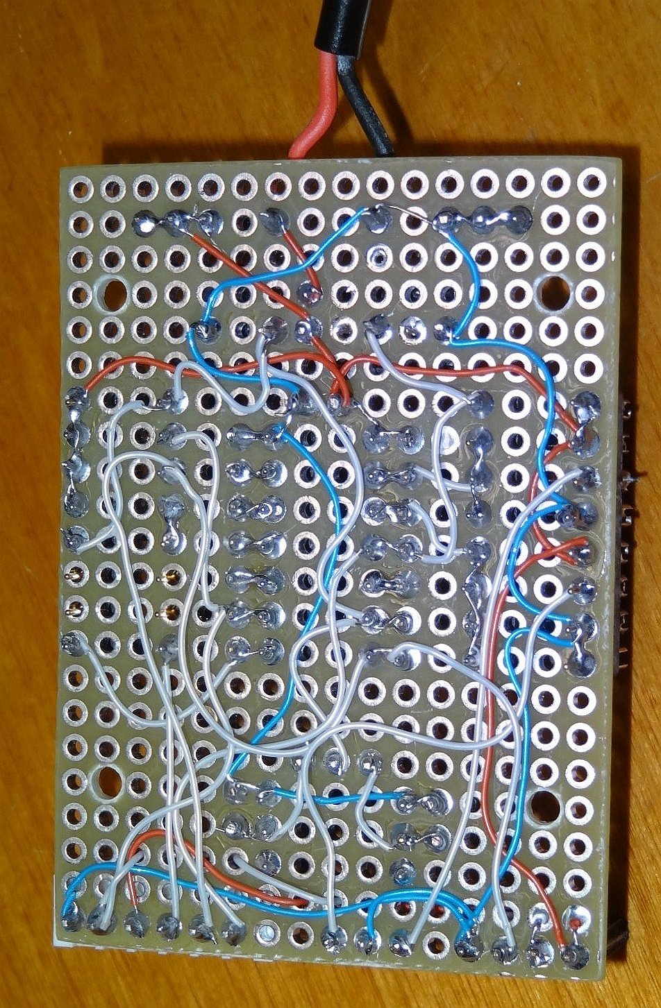
 ...ATtiny85 Testbed...
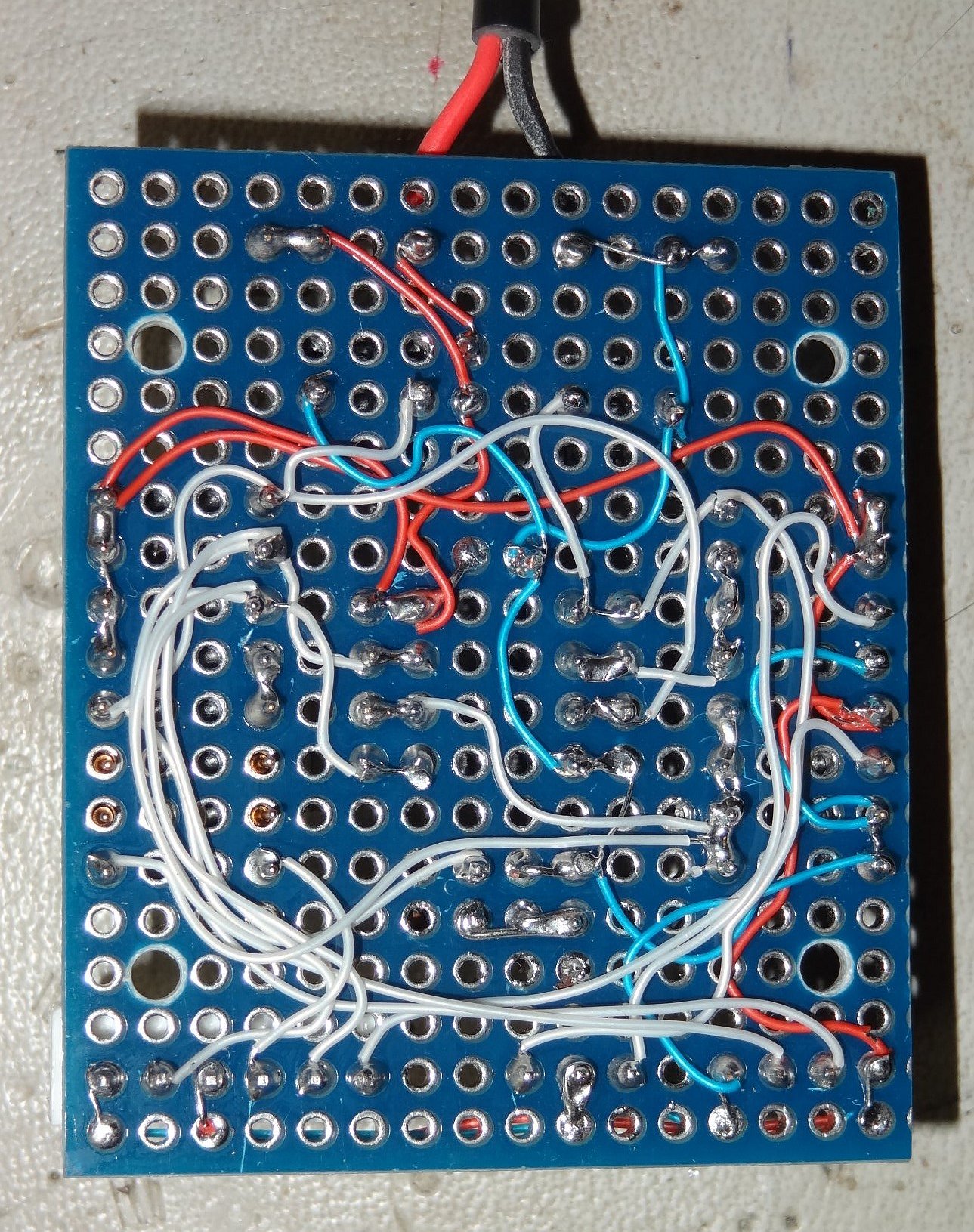
(click on any picture above to see larger version)
Operation
Once I've hatched an idea and counted pins and decided on which MCU, I'll write a crude sketch to
test my idea. I start small and simple, and build up my code by steps. One of the issues in
developing code for the Arduino IDE approach, and especially for the simple MCUs like the
ATtiny, is that there is no debug mechanism except to write code and check output pins. However,
these testbeds have Serial comms capability, and I'll generally sacrifice one MCU pin for Serial
Output at 9600b/N81. Then, I can send debug messages (including variable values) to a monitor of
some kind (like PUTTY running on my PC). Caution! Unless the testbed is running entirely on
battery power, always use an isolated USB-to-Serial converter. Note, it's best to use one
anyway, so that things like noise and hum don't send you down a long winding rabbit hole when
something doesn't work quite right. I use
this one: DSD-TECH p/n SH-U09C3, and it works for me.
You usually only need Serial Debug for development purposes, so I will generally give that pin an
alternate output-type function (like a tone for a beeper) and then select (in software) based on the
condition of that pin during initialization. If it is HIGH (meaning, a serial cable is connected),
it's a Serial Debug Output. If it is LOW, it's the alternate function (the tone). Thus, when
the serial cable is not connected, a user's push of the button might send a voltage value via morse
code to the beeper speaker. Or, the software might send an alarm "beep-beep" for a fault condition.
You get the idea.
Testing
I have written a sketch (arduino .ino file) to check/test/verify these testbeds, including the serial
output and every pin of the MCU. I'm not a programmer, so the code is not as compact as it might
otherwise be, and so uses almost every byte of available program memory on the MCU. It works on
both these testbeds mounted with the appropriate MCU. If you think it might be useful to you, you
can find it - here -. Please study the comments at the top of the file (it's text readable) to
understand the scope and how-to-use this software.
Hope you find the testbed useful, or at least that it gives you some ideas to try on your own!
73,
Monty N5ESE
dit dididit dit
Return to N5ESE home page
Overseer: Monty Northrup ...
 ... leave e-mail ...