When I built my new workshed, my intention was to have all-LED lighting, powered by a 12V battery
system. The shed was thus wired for low-voltage only. Two 100AH Lead-Acid batteries would power
the lighting system, and they reside under the shed in a weather-resistant battery box. Actually,
only one is connected to the lighting system at any given time, and if one runs out (it rarely
does), the other battery can easily be plugged in.
My further plan was to charge the 12V batteries from solar panels. Two years down the road, that
hasn't happened yet. So in the meantime, those batteries must be charged from a portable AC-line cord.
To that end, I needed a good float-charger system that would keep both batteries topped-off at all
times. I wanted linear regulators, but all the commercially available chargers were either
Switchers (read: RF-Noisy) or crude high-ripple chargers made for emergency lighting. I wanted to
be certain the chargers would not contribute to issues when I was working with something on the
bench. Additionally, I wanted something that could reside under the shed (near the batteries)
and be fine with that level of somewhat-protected, somewhat-not-protected weather-exposure.
So, if you want something done right (my father always told me), do it yourself. Out of that need,
came this Dual Charger.
The Dual Charger ended up with these features:
   - One package: 10"x10"x4" (Cheapo) Electrical Junction Box
   - One AC Cord, One Power Switch, and Surge Protection built-in
   - Two independent Linearly Regulated Chargers
   - Each charger capable of 50W continuous operation
   - Float-Charger approach; that is, Constant-Voltage 13.65V with linear Current Limiting (4A)
   - Visual Displays of Voltage & Current (actually, two displays - one for each charger)
   - Outputs are two cables (one for each charger) with PowerPole connectors.
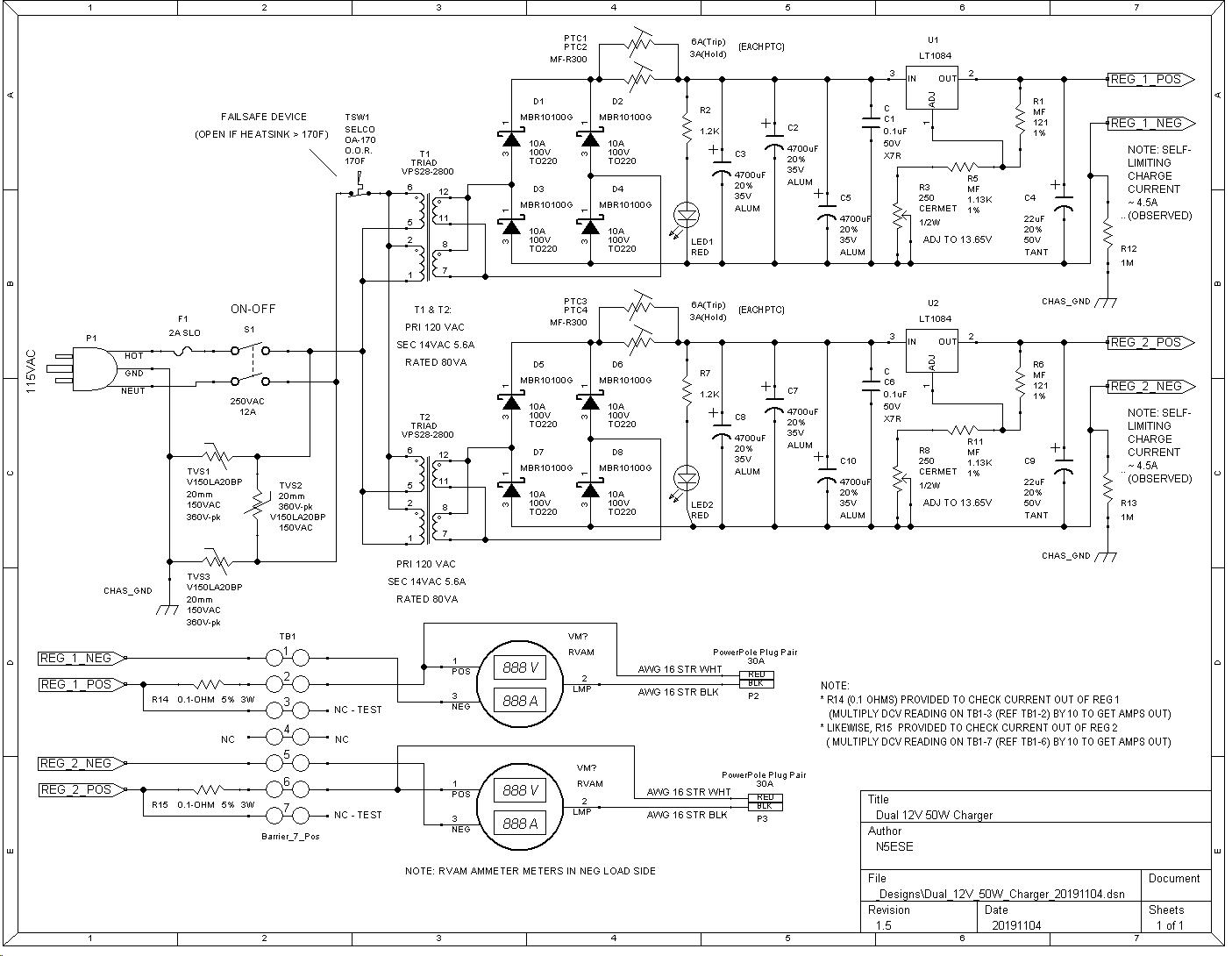
(click on picture above to see larger version)
From the schematic above, The AC line is switched and fused. Three MOV SPDs provide surge protection.
Thermostatic Switch TSW1, with O.O.R (Open-On-Rise) characteristic will disconnect AC power in the
event the main heat sink reaches 170 deg F (re 76 deg C)
Each of the two identical 50W chargers gets its own 80VA power transformer, a full wave rectifier, and
PTC resettable fuse. Filtering is included to bring the input ripple (to the regulator chip) down
to 3% or better. The 3-terminal linear regulator is an LT1084 tweaked to output 13.65 VDC. The
LT1084 provides current limiting which in practice occurs at approximately 4.5-5A. Ripple is well under
1% at full load (4A). The LT1084 (TO-220 pkg) is bolted to a single 10" x 4" x 1.5" finned heatsink
which in turn is bolted to the chassis (junction box) and can provide the required worst case 15
Watts dissipation (i.e., from each charge regulator).
Each of the two regulator outputs is monitored by a Voltage-Current monitor (made for RVs), the
Superbright p/n RVAM. The monitors are mounted so as to be visible for operator verification
of charging while in operation.
The unit is built into a standard gray steel 10x10x4 electrical junction box (available at electrical
dealers and HomeDepot and Lowes). The transformers and the AC-line-side components are mounted
in the box proper, and most other components (including the heatsink) are mounted to the access panel.
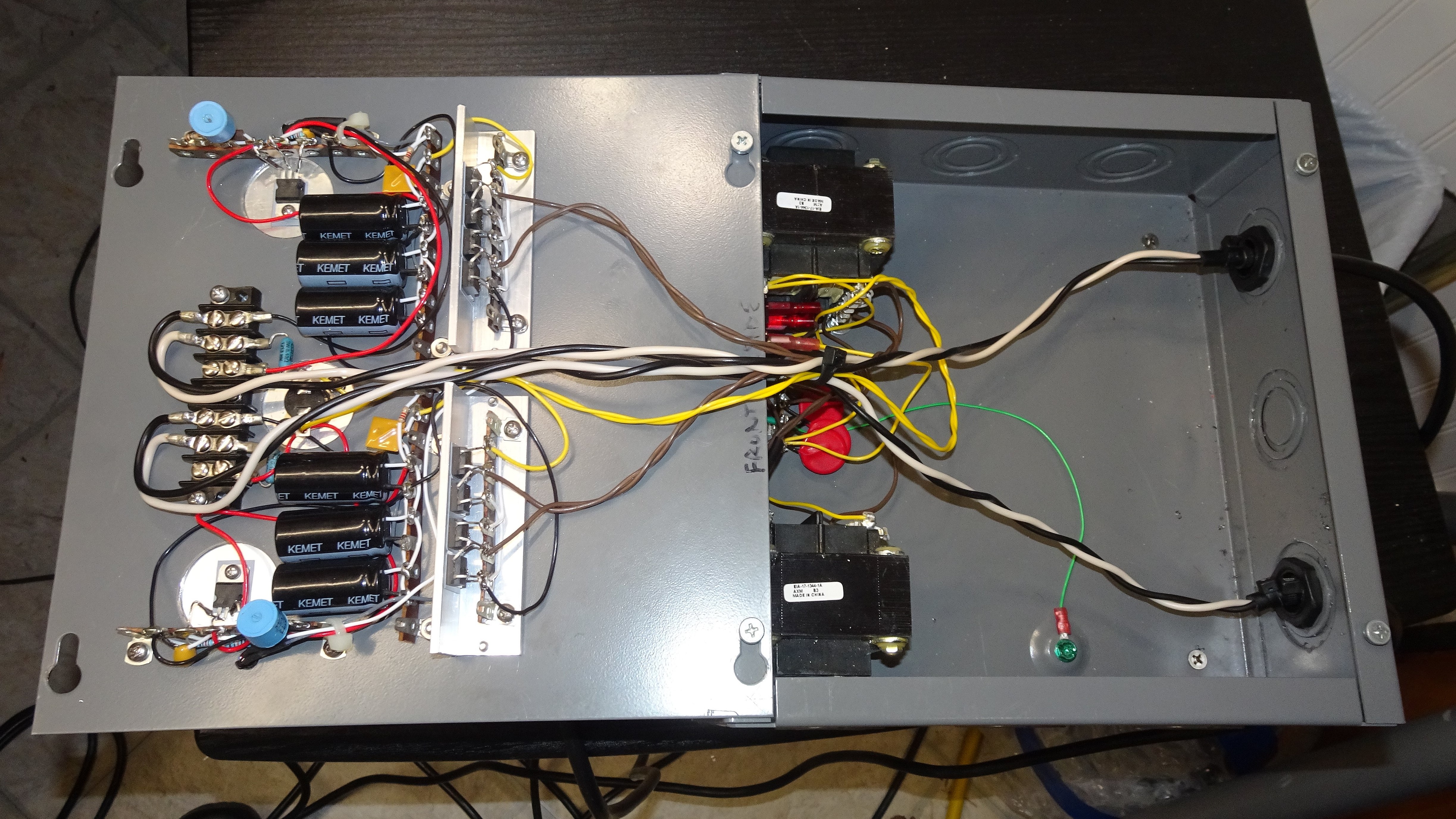
Below are some pictures of Construction:
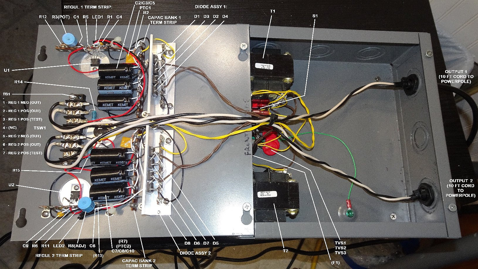
(click on picture above to see an Annotated larger version)
Below is a detail of components mounted on the panel. The rectifiers (4 ea TO-220 pkg mounted to a
piece of aluminum angle) are shown, left and right. The trimpot (blue cylinder) for setting the
regulator voltage (to nominal 13.65V) is soldered directly to a TV-type terminal strip (left &
right). In the center (between the two filter banks), you can see the circular opening where the
thermostatic switch is mounted directly to the heat sink.
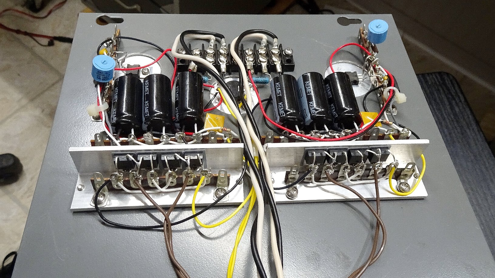
(click on picture above to see larger version)
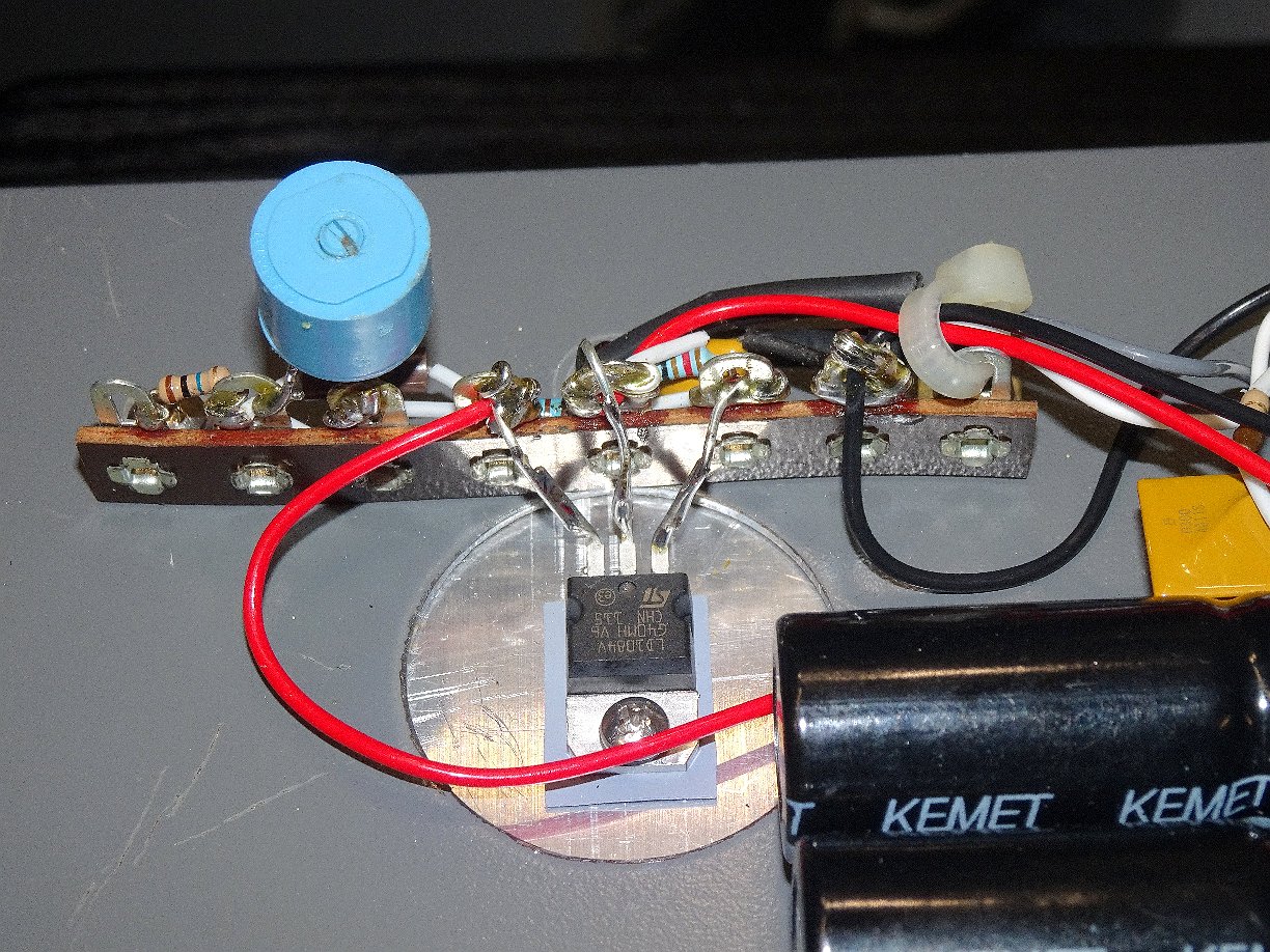
Below, is a detail of how one of the LT1084 regulators (TO-220 pkg) are mounted. A large-ish hole is
cut in the steel panel so that the regulator (with insulator) can mount flat onto the heatsink. Also can be seen
the TV-type terminal Strip which supports the smaller regulator components (and the trimpot).
(click on picture above to see larger version)
After the initial pix were taken, a modification to add voltage/current displays and an additional
(parallel) PTC resettable fuse were added. Those mods are annotated and depicted in - this image -
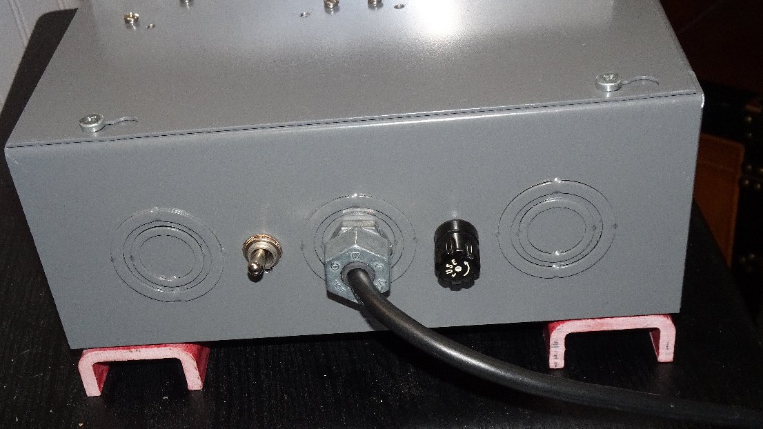
Below is a picture of the switch and AC-line input end of the completed assembly. Notice the
Fiberglass U-Channel on the bottom which serves to insulate and distance the completed assembly
from the soil (recall, the box is left under the shed, just as you see it).
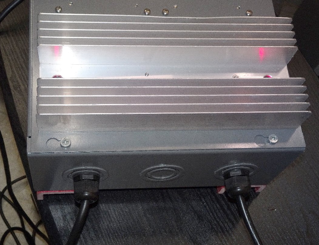
Below we see the opposite side of the enclosure (the output side). Cables are strain-reliefed and
sealed using gland-type bushings sized for the SOJ-type cable we're using. Each output cable is
a 2-conductor AWG 16 stranded, about 6-feet long, and terminated in a PowerPole-type
30A connector.
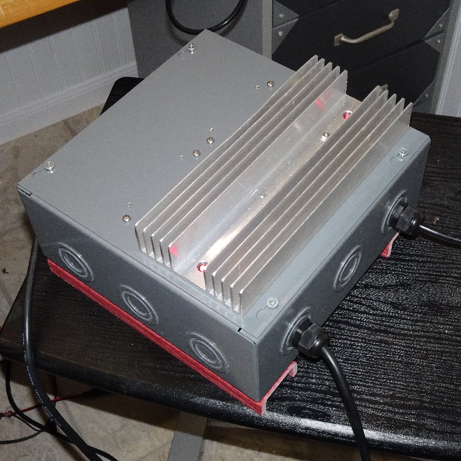
Below is a final overview of the completed enclosure. Notice that a RED LED (one for each regulator,
seen on each end of the heat sink) provides for a quick indication that AC-line power is
connected and applied to each respective regulator.
(click on picture above to see larger version)
This dual charger has been in service for about 4 years, keeping my two 100AH AGM batteries topped-off
and operating as expected. It operates reliably in spite of being exposed (beneath the workshed)
to our Texas summer temperatures which often exceed 100 deg F.
73,
Monty N5ESE
dit dididit dit