N5ESE High Performance Power Supply (2012)
For Vacuum Tube Receivers & QRP Transmitters
(click on any picture to see larger version)
I wanted to do some experiments on various receiver technologies (regen, superhet, etc.) using vacuum tube (valve) technology. I preferred an external-type power supply, line operated, that would provide ultra-clean DC Voltages for both tube and any included solid-state subcircuits. I wanted to feel certain that the power supply would not contribute to issues I might encounter while developing the receiver circuits. I settled on these target specs:
To accomplish this, we'll focus on the following topologies:
There are 5 non-hierarchial schematics in this design - they haven't been consolidated into one,
and there is no top level wiring diagram to show transformer and chassis wiring:
These supplies' schematics are shown below, in order, with notes.

(click on any picture to see larger version)
In the diagram above, we see the AC Line Input wiring with IEC input module (including fuse and EMI filter) and MOV-SPD protection on all lines and ground. Part numbers I used are annotated. Also shown (see graph) is the expected EMI performance of the input filter. EMI filtering on the AC line is always a good idea in the presence of RF signal (like in a ham radio shack). Also above, note the two output connectors (connected in parallel). These are Cinch/Jones-type connectors. Having two allows for the possibility of both RX and QRP TX from the same supply. A suitable candidate might be my Altoobs QRP Transmitter.
(click on any picture to see larger version)
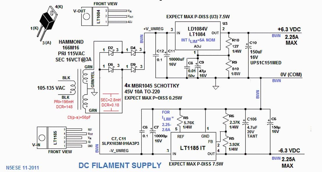
The Filament Supply is pretty straight-forward. An LT1084 for the Pos Regulator, and LT1185 for the Neg Reg. Both regulators have built-in current-limiting and short-circuit protection. The set voltage is actually adjusted to 6.5VDC on both, to allow for voltage drops across an external output cable. This is still well within the typical +/-10% filament spec. Heat sinking for the two TO-220 packaged regulator chips will be to one of the two fan-cooled high-efficiency heatsinks. As annotated above, max expected power dissipation for each heatsink is (7.5 + 7.5) = 15 Watts.
(click on any picture to see larger version)
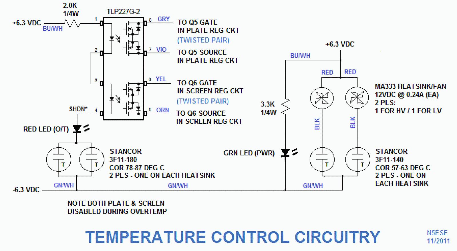
Anytime you're powering experimental or homebrew gear, you need to be prepared for overloads of all kinds - including over-temperature on heatsinks. The first level of protection is a mechanical COR (Close-On-Rise) thermostat sensing the high-performance heat sink temperature. If either heat sink temperature rises above 60 deg C (140 deg F), the respective fan is turned ON. and stays on until the temperture drops significantly. The Over-Temp scheme depends on another COR thermostat mounted on each of the high-performance heat sinks. If either O/T thermostat closes (around 82 deg C or 180 deg F), then current flows in the TLP227 Dual HV Opto-isolator, and the opto's output MOSFETs disable the Plate and Screen Regulators, thus removing operating voltages from the receiver/transmitter tube circuits.
(click on any picture to see larger version)
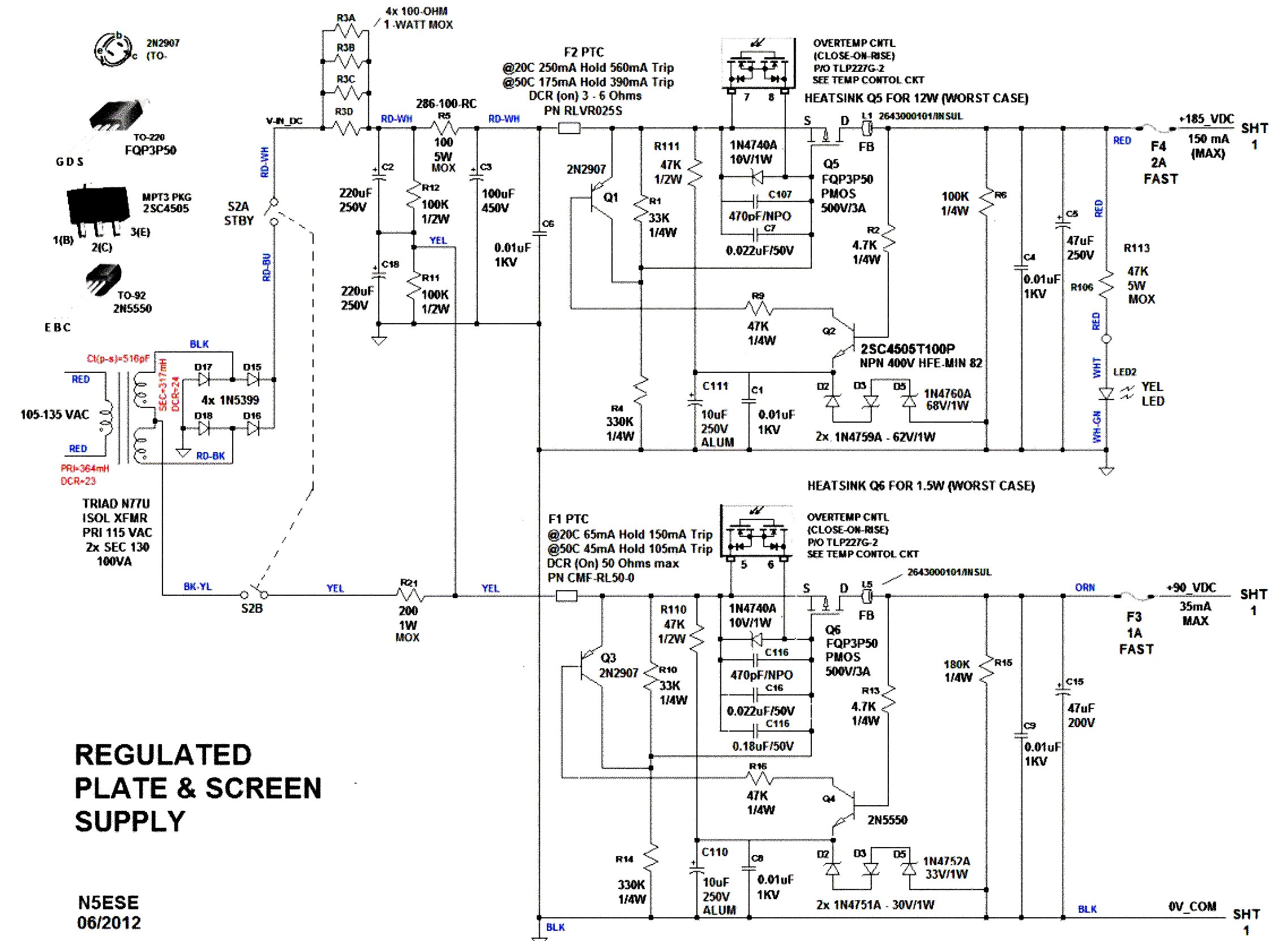
The first thing you'll probably notice is S2, a DPDT Switch (mounted on the chassis) which removes the Plate and Screen supply to provide a HV "Standby" capability. While at these relatively low plate and screen voltages (less than 200V) it's likely unecessary that the filaments to be fully heated before application of B+, nevertheless S2 provides this capability.
Circuit topology is the same for both screen and Plate supplies. Regulation is done by a classic zener-regulated transistor-driven regulator with HV PMOS MOSFET pass element. Series zener diodes determine the "set" output voltage, which will generally be +/-5% (set voltage). Line/Load Regulation is much better than this, however, due to the gain elements operating on the pass MOSFET.
Notice also the Optocoupler Output MOSFET (from the Over-Temp circuits) connected from Source-to-Gate of the MOSFET Pass transistor. These are normally very high impedance and have virtually no effect on either regulator. Upon an Over-Temp fault, these optocouplers effectively short gate-to-source on the pass transistor and thus shut down the plate and screen supplies.
Both Plate and Screen supplies are fused (fast-blo), mainly in case of an inadvertant short by an arc or a test probe mishap.
(click on any picture to see larger version)
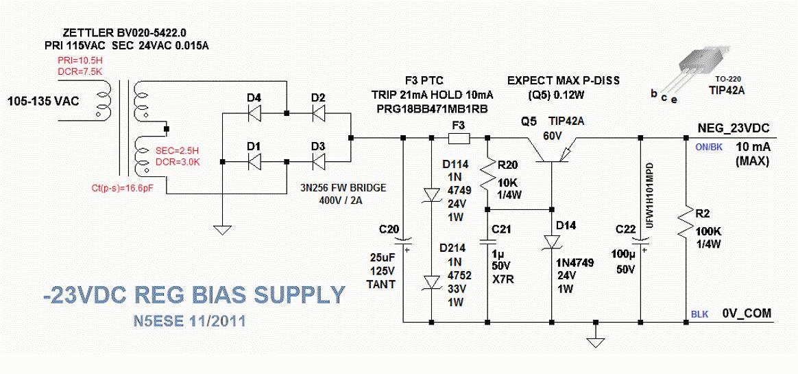
You may wonder why a bias supply in a Receiver Power Supply. Well, a fixed -22 to -25 VDC supply can be very useful for manual or automatic gain control, greatly simplifying the implementation. Also, it can be a perfectly usable QRP transmitter bias and/or keying circuit. Bias circuits typically draw less than a few milliamps, so our maximum 10mA spec is more than enough to serve the purpose. We use a very small 1/2 VA transformer mounted on the protoboard along with the "low-performance" zener-referenced discrete regulator.
(click on any picture to see larger version)
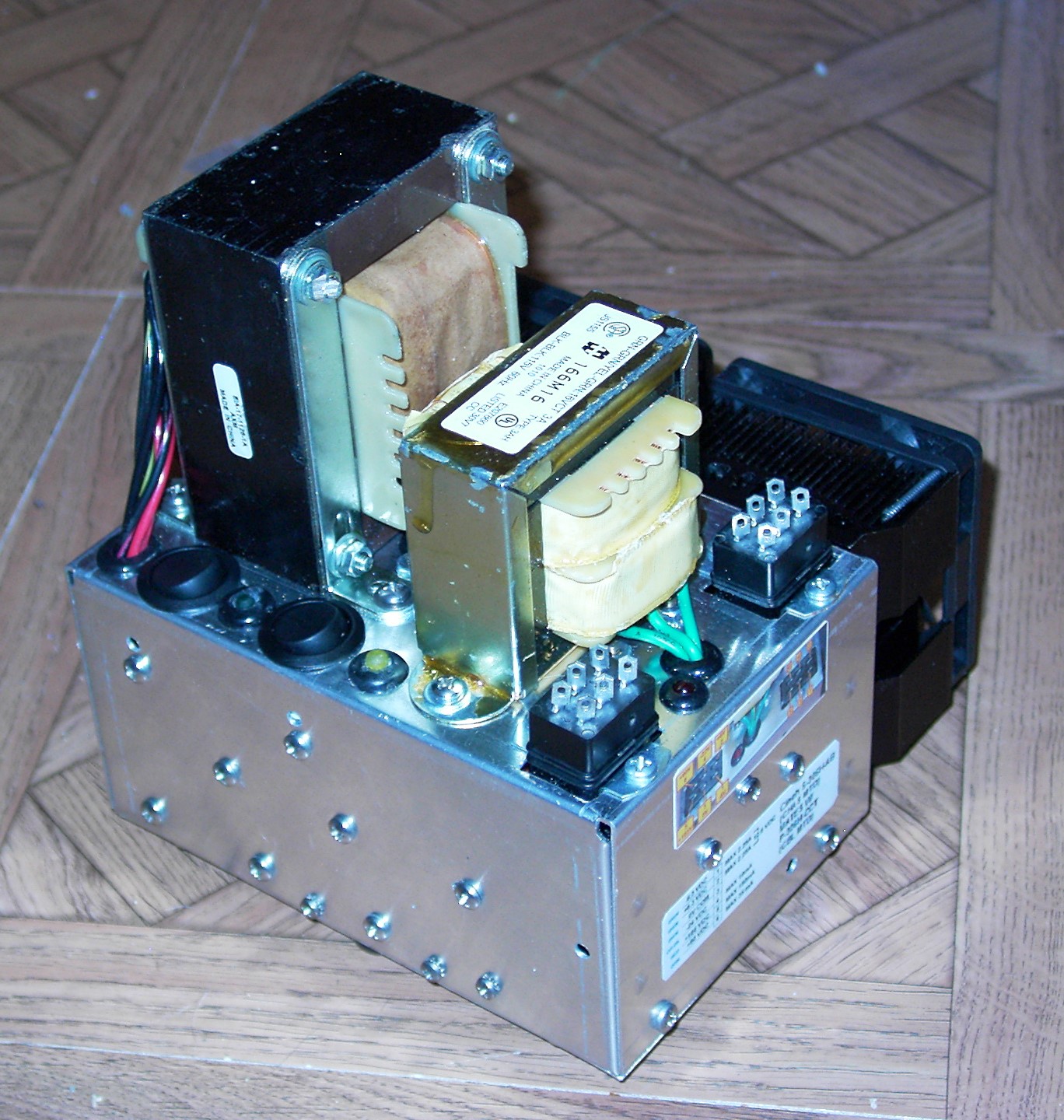
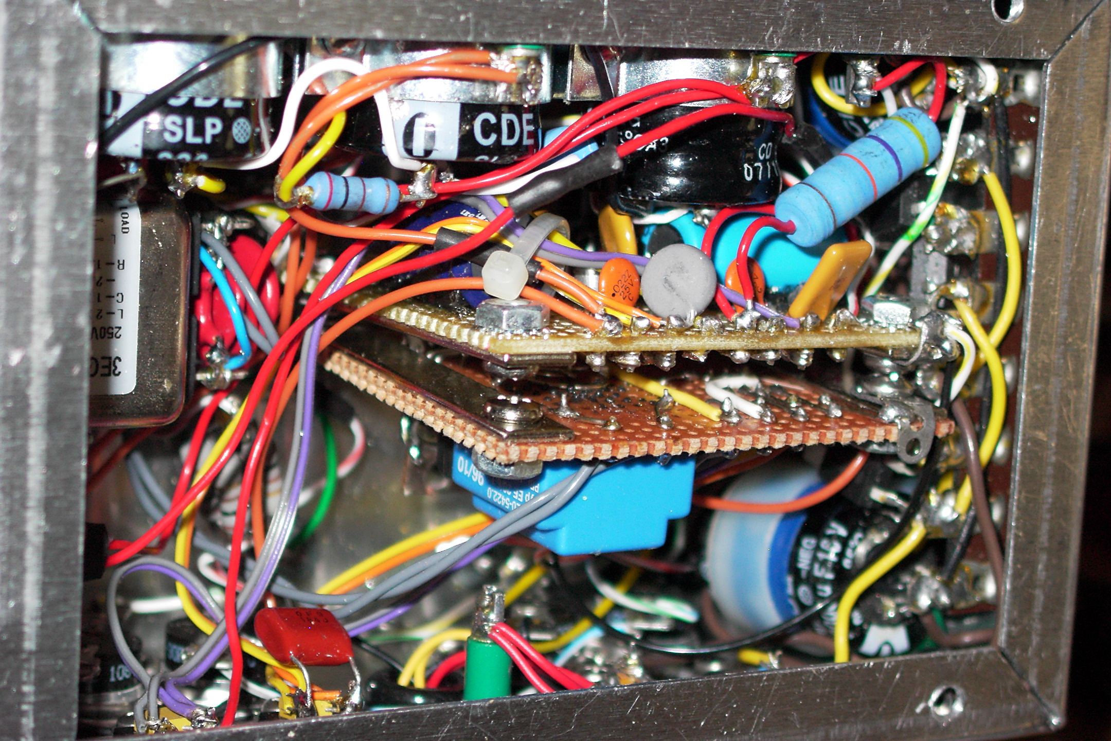
I selected a chassis that was minimally sized for the application, and as a result this was one of the most difficult wiring and packaging jobs I have ever done in 40+ years of homebrewing. Yeah, I did it, but it wasn't easy or pleasant. And 10 years after the build, I'm not sure I could pull it off again. Look at the picture above - a bottom-side view into the chassis. Jeez! So if you decide to replicate this project, select the next size up in chassis, and give yourself a break.
Looking at the picture above, you'll see two perf boards which comprise the Plate-Screen Regulator Board (top) and the Bias Supply (below it).
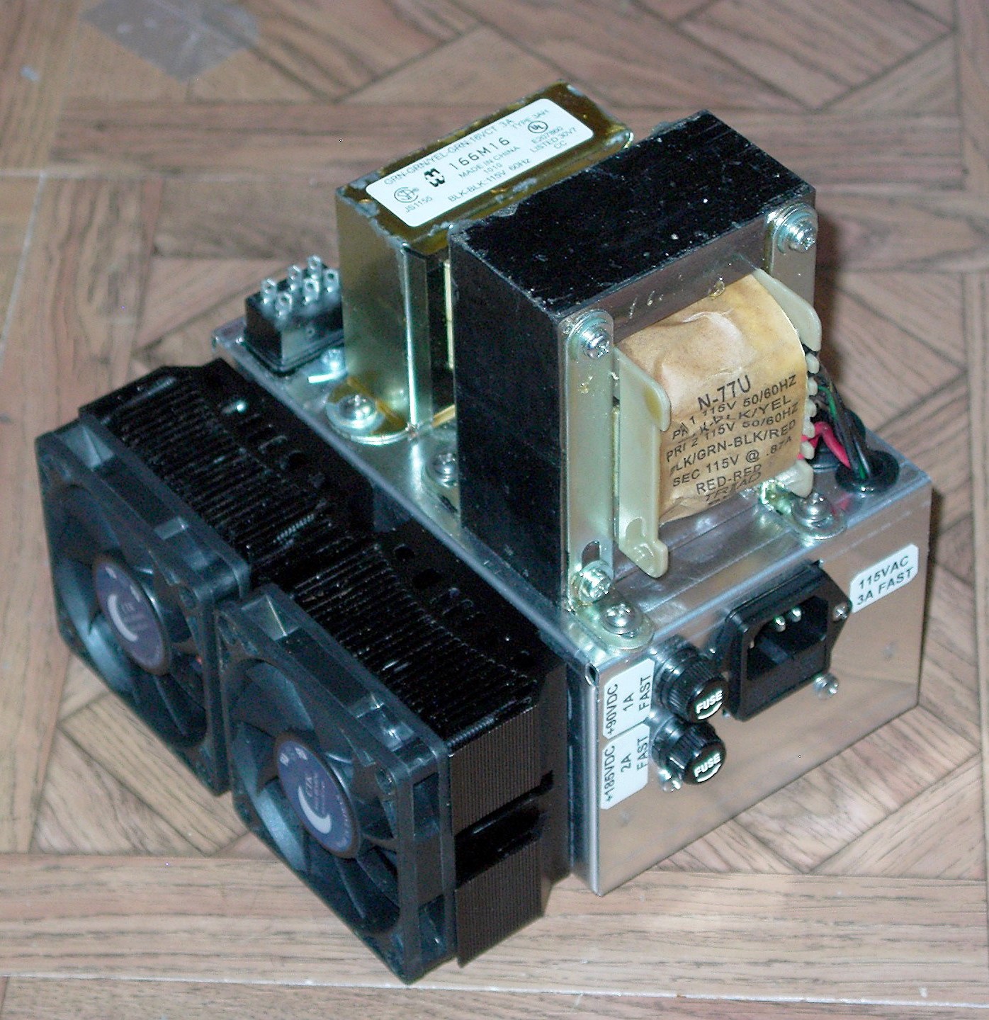
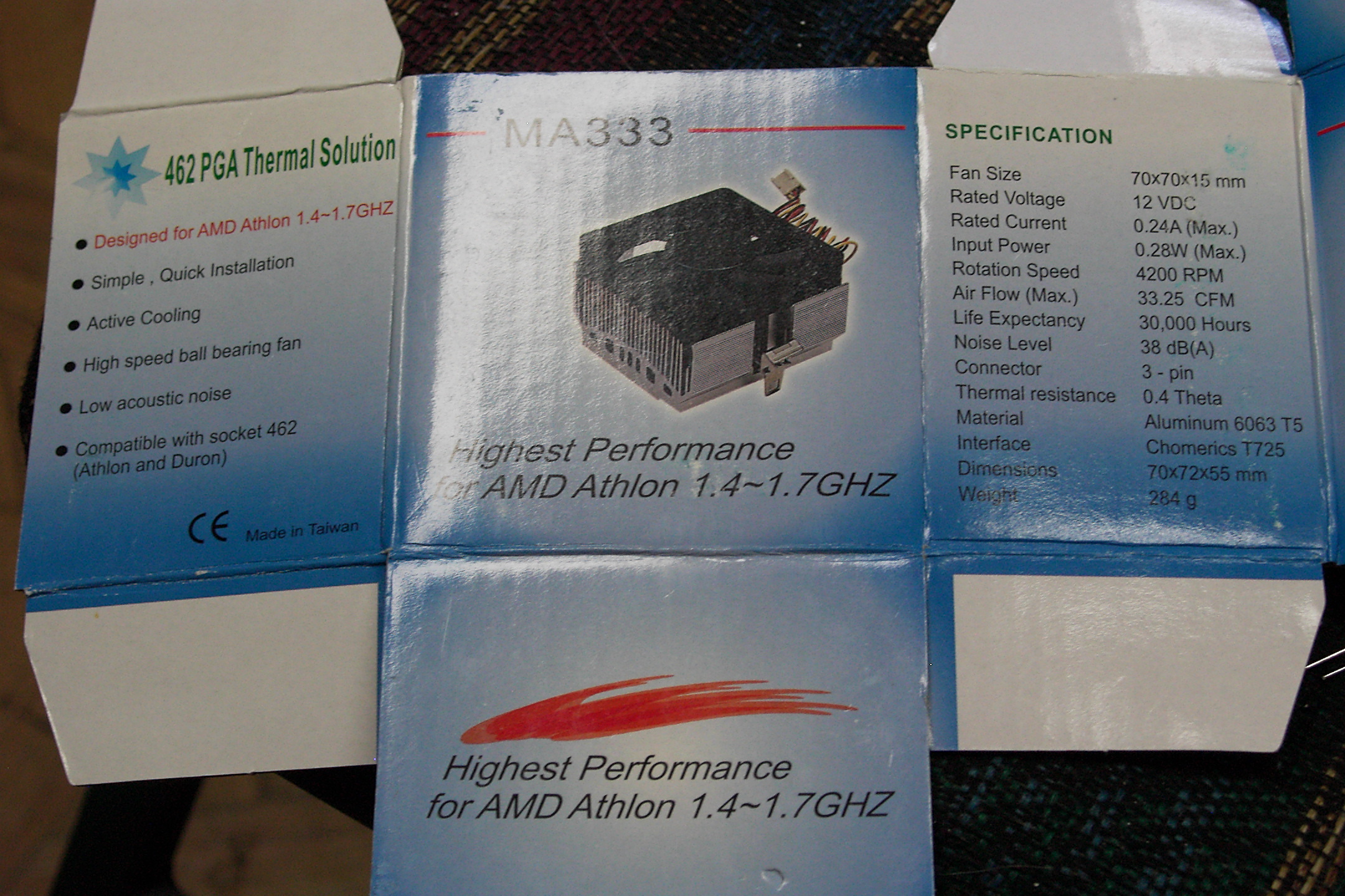
Below, you'll see the two high-performance fan-cooled heat sinks mounted to the chassis on one side (underside view). The Heat sinks are p/n MA333 with dimensions as shown on their packaging the next picture.

(click on any picture to see larger version)
(click on any picture to see larger version)
Below, the Plate/Screen Dual Regulator Board (Annotated, built on Perf Board):
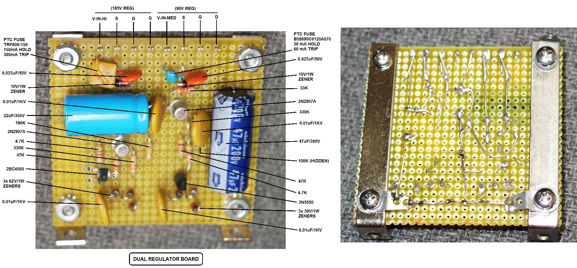
(click on any picture to see larger version)
Below, the Bias Regulator Board (Annotated, also built on Perf Board):
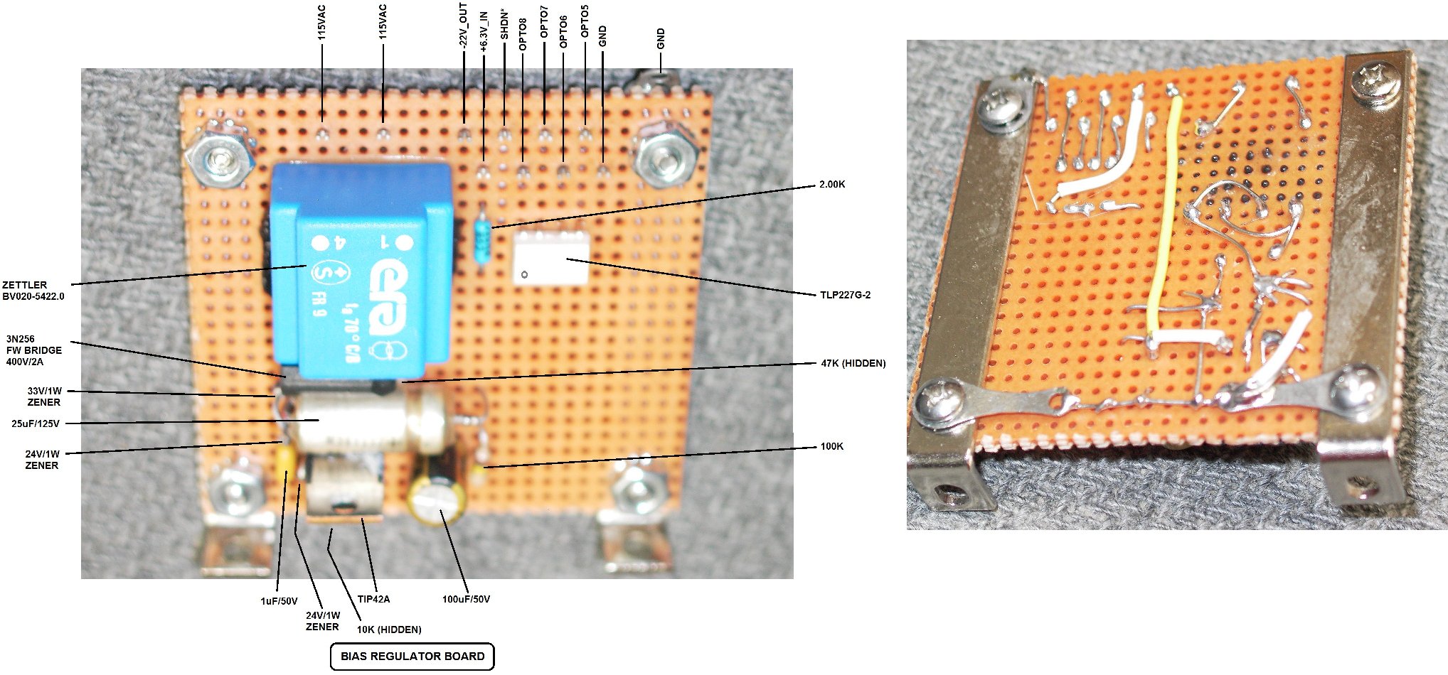
(click on any picture to see larger version)
Below, chassis partial assembly showing detail of two Heat sink assemblies mounted and ready for wiring. Notice two Thermostats on each heat sink, as well as two regulator chips or two pass transistors (all TO-220 packages)
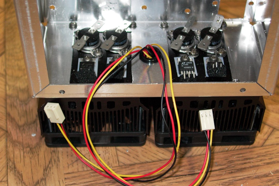
(click on any picture to see larger version)
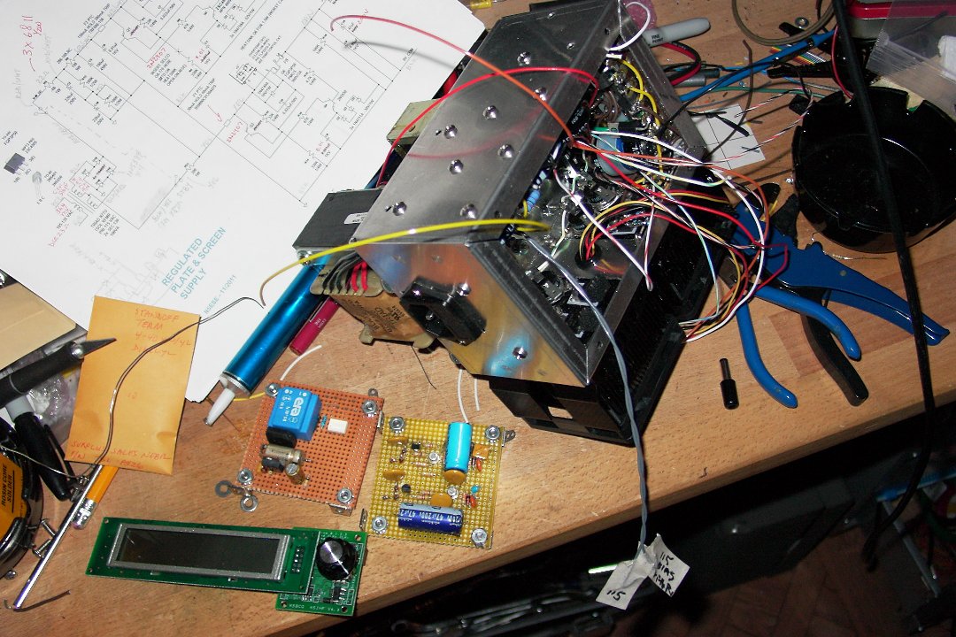
Below, chassis partial assembly just prior to installation of the two regulator perf boards.
See, it really is crazy crowded. By the way, the LCD is part of a different project, and just happens to be in the picture.
(click on any picture to see larger version)
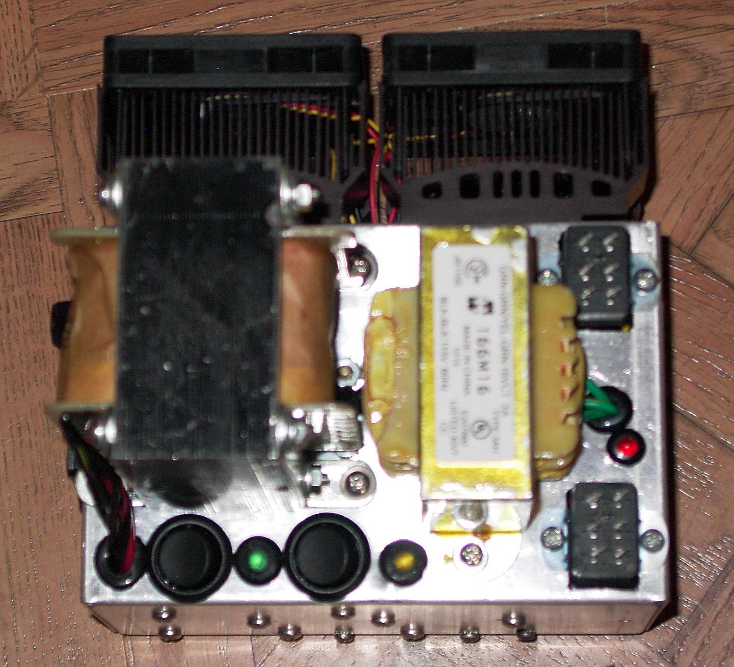
Referring to the image below, on the far right you see two 6-pos "Jones"connectors. On the Chassis side, these are sockets. Currently, there are two plugs installed (being used as test points). These will solder to multiconductor cables which on the far end would then mate with the target receiver (or other equipment).
On the lower-left there are two round rocker switches and two LED's. The left switch is AC Input Power, and the adjacent green LED is the power ON indicator. Just rightward of that is the "Standby" switch for Plate and Screen supplies, and the adjacent yellow LED is the HV power ON indicator. Lastly, to the right, between the two connectors, is a red LED which illuminates only if an Over-Temp fault occurs.
(click on any picture to see larger version)
I hope you enjoyed this project. For me, this has been a "go to" power source for many tube-type projects, and has never given me any problems.
73,
Monty N5ESE
dit dididit dit