This page will always be !! UNDER CONSTRUCTION !!
On this page, I'm not going to try to show detail pictures of how I did things. I'll just share my notes - hope you can
make sense of them - and you're welcome to contact me for more info if you have a question.
Getting started, I'll share my notes of what I've done with my own HW-16, both repairs and mods:
Actions 20200808 (N5ESE) re misc nagging repairs:
Issue: Audio output is intermittent (Tube Socket)
Fix: Replaced 9-pin Tube Socket at V6 - works solid now
Issue: Volume control froze up
Fix - replace 500K Volume Control (w/ power switch) - works good!
Issue: Alignment
Fix: Aligned RX & TX (did not do neutralization of final)
Actions 20200812 (N5ESE) re add switch for xtal or exte vfo:
Issue: When using external VFO, can't use XTAL.
FIX: Add smal SPDT mini-toggle at rear panel; UP selects external
VFO; DOWN allows front panel xtal.
Actions 20200828 (N5ESE) re mods to reduce key clicks:
Issue: Loud and distracting Key Clicks in sidetone when sending
with External DDS-VFO; Believed RF Feedback causing issue.
Fix 1: Add Key Click Filter betwwen external Key and internal
keylines. Filter consists of Butterworth LPF (PI-form) with
0.47uF/400V Poly on input and output, with L=1.5mH shielded
Toroidal Epoxy encapsulated inductor. Inductor DCR (meas)
2.5 Ohms. Mounted on inside wall of chassis rear panel.
Fix 2: Add Butterworth LPF (PI-form) at 6.3VAC Filament Supply
(where it leaves the chassis to go to the VFO). Design Fc
approx 750 KHz (24 dB down at 3.5 MHz). Consists of 11.5 uH
coil and 2000 pF 100V (2x1000pF) disc capacitors (Input &
Output). Inductor rated 0.8A with measured DCR of 0.7-Ohms.
Mounted on inside wall of chassis rear panel.
Fix 3: Add Butterworth LPF (PI-form) at Speaker output (includes
Headphone Jack. Design Fc approx 650 KHz (24 dB down at 3.5 MHz).
Consists of 10 uH coil and 2000 pF 100V (2x1000pF) disc
capacitors (Input & Output). Inductor rated 1.5A with measured
DCR of 0.9-Ohms. Mounted on inside wall of chassis rear panel.
Fix 4: Moved AC Line Fuse because needed that rear panel space to
implement above fixes. New fuseholder. Same 2A 1-14" Fuse.
Note: Clicks in sidetone when keying are 99% gone!
Actions 20200830 (N5ESE) re repair/mod - R46 :
NEW ISSUE: Rcvr highly attenuated. Maybe related to keyline changes -
found R46 (47K/1W) dropping B+ to Keying Circuit way too
much - Removed and it measures open circuit (but looks fine)
Fix: Replaced R46 with 47K/2W Carbon Comp. Rcvr now works fine.
Actions 20200831 (N5ESE) re misc issues:
Issue: Tube socket at V4 flaky; (intermittently no receive on warm-up -
have to wiggle tube to get it to work)
Fix: R&R V4 7-pin Socket
Issue: AF Amp (V6) breaks into oscillation with large signals
Fix: Dress Blue Wire to AF Xfmr straight up from board and tight
against XFMR Core. Also, moved 6.3V Filament Wires from
Sidetone Oscillator from V6 to V5, and raised that subassembly
up to provide 1" clearance to big PCB (in case some coupling
occurring there) - No oscillations anymore!
Issue: Final needs Neutralization
Fix: Perform neutralization procedure in manual pg. 41-42
(needed it) - OK
MOD: Replaced incandescent bulbs with LED (warm white) bulbs
(2 places, 6.3VAC/DC bulbs equivalent to No. 47)
Actions 202020912 (N5ESE) re classic HW-16 mods:
Issue: Improve Rcvr Sensitivity and noise per ER-Mag May-June 2012
MOD: Replace R42 (V4 6EW6 IF Amplifier Screen Voltage Divider):
BEFORE: 5.6K 1/2W Carb Comp
AFTER: 47K 2W Carb Comp
"increases the screen voltage at 6EW6 to more correct level"
MOD: Replace R21 (V1 6EW6 RF Amp Screen Dropping Resistor):
BEFORE: 22K 2W Carb Comp
AFTER: 10K 3W MOX
"increases screen voltage on V1 and some following stages"
MOD: Replace R24 (V2A 6EA8 Mixer Grid Leak):
BEFORE: 10K 1/2W Carb Comp
AFTER: 47K 1/2W Carb Comp
"reduces loading on the RF AMP, and reduces mixer noise"
MOD: Replace R28 (V2B 6EA8 HFO Grid Leak):
BEFORE: 1 MEG 1/2W Carb Comp
AFTER: 330K 1/2W Carb Comp
"reduce receiver drift"
NOTE: Realigned receiver front end L1-L2-L3 (very minor adjustments)
Actions 202020912 (N5ESE) re Power Control Mod *but* SEE NOTE:
NOTE: !!! This MOD was stripped out and done a different way (V2)
See ACTIONS 20200921
ISSUE: Not much range in Output Power Adjustment. Mod puts
full screen voltage on final V9 6GE5 (rather than pot
controlled screen voltage) and uses the pot control to
instead control the screen voltage on V8 6CL6 Driver.
Mod supposedly allows controlling Output Power down to
3 or 4 watts)
MOD: * Move red wire on Wiper Contact of R13 (Power Control)
to the high-side contact of pot (which goes to +310V
bus. V9 Screen now has full level screen voltage at
all times
* In the V8 Driver circuit, remove the end of R6 (22K/2W)
from the terminal strip with the +310V Bus.
* Install a dialyl turret terminal on the divider wall
between V8 & V9.
* Connect the free end of screen dropping resistor R6 to
the turret terminal. Assure clearances.
* Connect the turret terminal and R6 to the wiper of R13
Power Control Pot.
NOTE: The following range on R13 Wiper is observed during
Transmit: 153 to 253 VDC (FCCW to FCW). Don't see much
difference in BEFORE/AFTER Final Plate currents - maybe
slightly higher, especially on 15M. Not yet verified that
output power can be controlled lower than before.
Actions 202020912 (N5ESE) re Add Select-O-Ject SOJ Audio Filter:
Issue: Mods to install Select-o-Ject (SOJ) AF Filter Board:
MOD: Drill 1/2" Hole in Chassis (Right-Front) to accommodate
up to 6 RG-174 Coaxes; install rubber grommet.
MOD: Add 2 each 1" 4-40 brass/nickel standoffs for mounting
SOJ Board on bottom of chassis, near the Sidetone Board
Actions 202020913 (N5ESE) re Select-O-Ject SOJ (continued):
Issue: Mods to install Select-o-Ject (SOJ) AF Filter Board.
MOD: Install SOJ Board, chassis underside, using 1" standoff hardware
similar to the Sidetone Board's mounting.
MOD: Install SOJ Selectivity Pot (500K Audio Taper) on front panel,
Selected Pot has an integral DPDT push-push switch to provide
SOJ Bypass/ON functionality. (p/n Bourns PDB185-GTR01-504A2)
NOTE: All audio interconnections to SOJ Board are accomplished
using RG-174 shielded cable. All Cables passing from topside to
bottomside chassis, pass through the newly installed 1/2"
Grommet (see above). The SOJ Board also requires 6.3VAC
filament power and 165 VDC for plate Voltage. See Schematic:
file: SOJ_MOD_FOR_HW-16_20200912.pdf
Actions 202020913 (N5ESE) re one more Select-O-Ject SOJ related Mod:
Issue: After installation of SOJ Board, observed that +175V
(normally, about +165 VDC) is only about 110V:
MOD: Add 39K 2W Carbon Comp in parallel with existing 33K res R207
NOTE: If SOJ is removed in future, this new resistor will need
to be removed.
Issue: After installation of SOJ Board, observed that +310V
(normally, about +304 VDC) is only about 298V:
MOD: Add 560-Ohm 1/2W Carbon Comp in parallel with existing 220-Ohm
res R207
NOTE: If SOJ is removed in future, this new resistor will need
to be removed.
TESTS GOOD!
Actions 20200921 (N5ESE) re Revised Power Control Mod:
NOTE: This is the new (V2) Power Control MOD
ISSUE: Not much range in Output Power Adjustment. The MOD from
Electric Radio Magazine did NOT work as advertised, and may
have overtaxed the old carbon pot, and maybe the Final V9.
MOD: * R&R Power Level Pot R13 (Removed: orig 15K Carbon Pot;
Replaced with: 250K 2W CERMET Pot (Bourns 3852A-282-254AL)
* On the top side (chassis, between V7 & V8) install a dialyl
Turret Standoff. This will be the tie-point for V9 6GE5
Final's Screen Voltage.
* Move red wire (with insulation sleeves, coming from V9
screen through hole in chassis) to the newly installed
dialyll standoff.
* The other red wire which carries +310V B+ (from underchassis)
goes to the TOP (leftmost, as viewed from front) terminal
of the newly replaced pot R13.
* Remove the installed R14 and replace it with a 499K 1%
1/4W resistor (p/n RN55C4993F). One end connects to the
pot's chassis ground lug, and the other connects to the
bottom (rightmost) terminal of pot R13.
* In the V8 Driver circuit, relocate R6 (22K/2W) back to
the terminal strip with the +310V Bus. (V8 6CL6 Driver
is now returned to original screen wiring)
Note: R6 was replaced with a new Carbon Film 22K/2W
resistor, as the old Carbon Comp resistor had aged up
to 29K.
* Remove the dialyl standoff previously installed under
chassis for R6. The standoff is no longer used.
* Drill holes in the under-chassis divider plate to mount
the new Power Control Board. This new board uses a Power
Darlington as a pass element, which mounts using a TO-220
Silicone Insulator kit.
* Wire the newly installed pot R13 and the newly installed
power control board per the new Power Control Schematic:
file: HW-16_Power_Control_MOD_20200921.pdf
* Output of the Power Control Board routes (red Wire) to the
newly installed dialyl Standoff (top chassis). That standoff
serves as the tie-point for v9 6GE5 Final's Screen Voltage.
NOTE: The following range on Power Control Board Output
(i.e., V9 Final's Screen Voltage) was observed:
Transmit: 89 to 253 VDC (FCCW to FCW).
Input Power is controlled smoothly from I-plate 180 mA down
to 40 mA (re front panel meter).
Output power is observed to be controlled down to about 8
Watts out, but further reduction in Power Level Control will
cause power to abruptly drop to 1 Watt (No in-between settings).
However, 5W QRP can be obtained by reducing the power to 8 watts,
and then detuning the 'TUNE' control leftward (CCW from resonance
dip), to get 5W. Note: "Leftward" is towards more capacitance.
Actions 20200922 (N5ESE) re Add LED-type Zero Beat Detector:
NOTE: This is the new Zero-Beat Tone Detector MOD
ISSUE: Operator has "issues" zero-beating VFO to match received frequency.
This gizmo is set to detect a 700 Hz tone, providing a RED LED
indication when you are within 10 Hz of that freq. If you first
tune the received signal for 700 Hz detection, then when you
adjust the VFO to match 700 Hz, the HW-16 will be matched in
transmit frequency.
MOD: Zero-Beat Tone Detector Board is a LMC567 PLL-based board
built on a 2x2" proto board. Solid State. It is described in schematic:
file: HW-16_Zero-Beat_Tone_Detector_20200922.pdf
MOD: Fabricate an L-Bracket (approx 3" Tall and 1/2" wide) to mount
the new ZB Tone Detector Board at 2 points. The L-Bracket will
then mount on Chassis topside, using the hardware that also
mounts the dial lamp holder on the dial-side. See Pix.
MOD: Fabricate another bracket (I used two each Keystone 780
L-Brackets) to hold the LED in place behind the translucent
strip of the main tuning dial.
MOD: The ZB Tone Detector Board is powered by 6.3VAC from the filament
power supply. Use a Shielded Twisted pair, as this will route
from topside to bottomside chassis, through the same grommet that
the audio lines for the SOJ pass. Pick up the 6.3VAC and return
ground near V5, where the other boards (S/T & SOJ) also get 6.3VAC.
MOD: Audio for the ZB Tone Detector board is taken from the grid of
the 6HF8 Audio Amp (V6 Pin 7). Use RG-174 for shielded audio
from E23(E22) on the ZB Tone Detector Board to the Pin 7 end of
V6's 330K gridleak resistor. Make this run entirely topside.
See Pix.
MOD: Mount the LED via pair of AWG 30 wires, on the bracket fabricated
earlier, and just behind the dial, where it can be seen from the
front when illuminated.
NOTE: The actual Tone Detection Freq was adjusted to 893 Hz, to match
the peak response of the Select-o-Ject (SOJ). A certain minimum
volume is required to meet the thresholds of the PLL chip.
Scaling of the input network (of the ZB Tone Detector) has been
designed to work with the typical audio levels seen at the grid
of V6. Weak signals (or signals in heavy noise) may not meet
the requirements of the PLL for reliable detection.
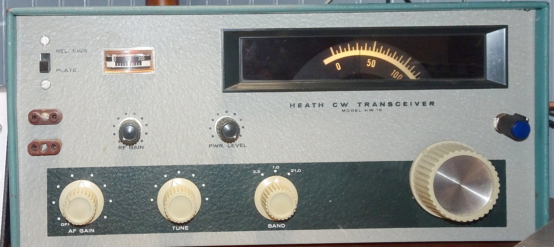
Heathkit HW-16 80/40/15 CW Transceiver (no SN)

Actions 20100822 (N5ESE) re Sidetone:

   Modify to install new sidetone oscillator and rear panel switch to select new or orig S/T:
      - See  my vintage sidetone page
   Note: Orig/New S/T select switch is added on the rear chassis I/O panel, midway between
         (and above) the SPKR and PHONES jacks

Actions 20120909 (N5ESE) recap aging electrolytics:

   Hayseed Recap kit installed 20120909
[ Hayseed = Tom N0JMY, Fredericksburg, IA Hayseed Hamfest ]
1. R&R C204 Multicap Can Electrolytic:
- OLD 47uf 350V; NEW 47uF 450V
- OLD 80uF 300V; NEW 85uF 350V
- OLD 80uF 200V; NEW 85uF 250V
2. R&R C202:
3. R&R C203:
- Disconnect old C203 50uF 350V Can (Leave installed for aesthetics)
- Install NEW C203 47uF 450V Radial (under Chassis)
4. R&R C201 Multicap Can Electrolytic:
- Remove old underchassis cap (2x 20uF 150V)
5. Note: C68 (Cathode decoupling Capacitor) was replaced earlier:
- Remove 10uF 16V Alum Electrolytic
- Install 2 ea parallel 4.7 20V Tantalum
73,
Monty N5ESE
dit dididit dit