I ran across an excellent DIY milliohm meter by Louis Scully of Scullcom Hobby Electronics.
Most of the experimentation and debugging had already been done, which resulted in a very stable milliohm
meter (stability is one of the biggest measurement issues for milliohm meters). Louis also provides
a "shared project" printed circuit design, which he has uploaded to OSH Park (a PCB house) and
you can order that board (v1.41) at this link: OSH Park v1.41. However, another designer (Barbouri) has made
improvements to the board, and those are described - here - and that version of the board (v1.5) can also
be found at: OSH Park v1.5. That last version (v1.5) is the one I used.
Back in my working days, I had access to and used an HP 4328, a lab-grade analog milliOhm meter
with a special probe that measured 0-2 milliOhms (at the lowest scale) up to 0-20 Ohms (at the
highest scale. It was useful for two things
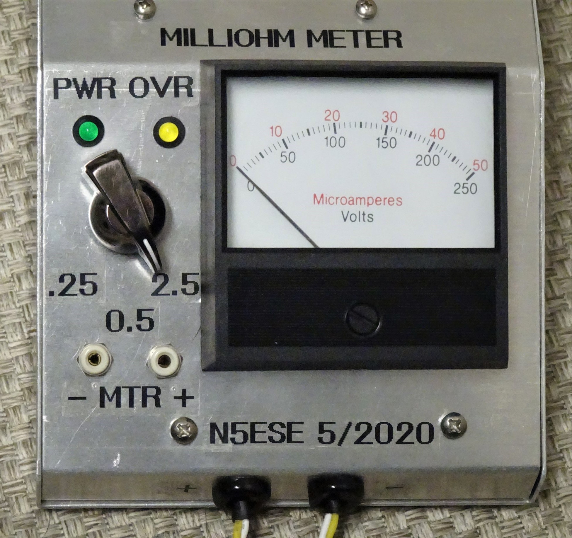
This Analog Meter MilliOhm Meter utilizes the Scullcom design (& PCB), but instead of a 0-2V DC
4-1/2 Digit DPM (Digital Panel Meter), it uses an Analog Driver Circuit (re N5ESE design) to drive
a 0-50 µA Meter.
The output of the the main Scullcom/Barbouri MilliOhmmeter Board is a DC Signal: 0-4.5V, representing
0-4.5 Ohms.
This analog version circuitry buffers that 0-4.5V signal with a switched gain difference amplifier,
to provide a 0-2.5V DC Signal for driving the 0-50uA Meter. The meter used has two scales,
0-50 and 0-250. The gain select switch then provides 3 positions:
A very thorough description of the Scullcom/Barbouri MilliOhmmeter Board (including schematics)
exists - here - and as far as our own schematic goes, we prescribe that the Scullcom/Barbouri board
0-4.5V output becomes our inputs MTR+ and MTR-. We will, of course, also supply power to the
Scullcom/Barbouri board.
Here's our schematic:
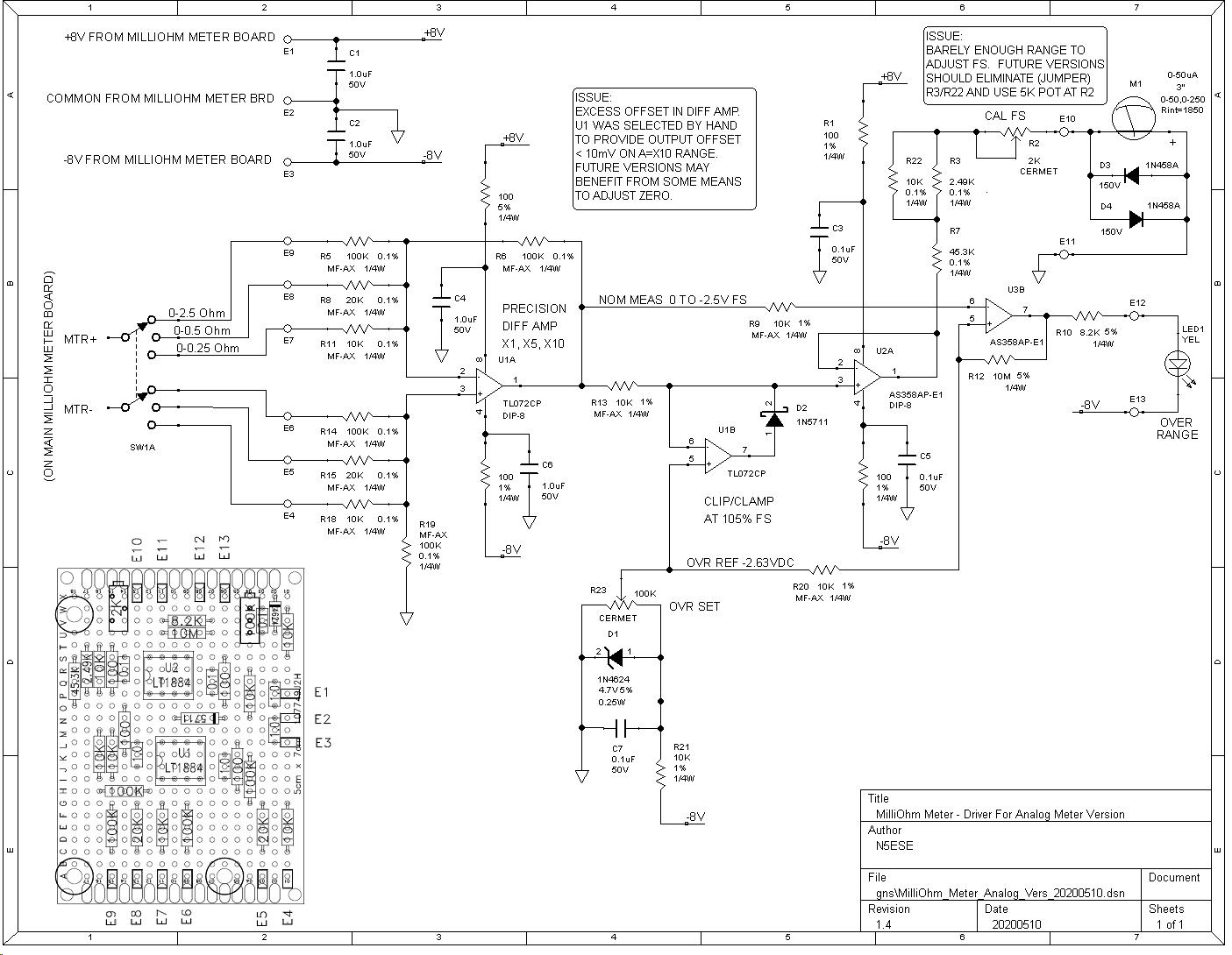
(click on any picture to see larger version)
Power for our board is provided by the Scullcom/Barbouri MilliOhmmeter board, which develops +/-8V.
Looking at the schematic, the MTR+/MTR- signal from the Scullcom/Barbouri milliOhmmeter board supply a
0-4.5V signal representing 0-4.5 Ohms. Scullcom intended to drive a 0-2V 4-1/2 digit meter, while
we intendto drive an 0-50uA analog meter with scales of 0-50 and 0-250. Further, we intend to scale
that to select one of 3 measuring modes: 0-250 milliOhms, 0-500 milliohms, and 0-2.5 Ohms.
To that end, we take the DC signal coming from the Scullcom/Barbouri board and route it to a precision
difference amplifier (U1A) with gain of X1, X5, & X10 (accurate to with +/-0.2%). That in turn
feeds U2A which will then drive the 0-50uA analog meter we have selected. U2A output circuit has
provisions for calibration of the meter at full scale. U1B and Voltage Reference D1 work together
to clamp U2A and prevent it from overdriving the meter beyond about 105%. Thus, with nothing
connected at the milliOhm probe, output would be full scale 4,9V (approx), but our clamp circuit
will prevent the meter from being damaged by excessive drive. At the same time, D1 and U2B form
a comparator circuit, and if that aforementioned overdrive occurs, U2B will illuminate a Yellow
LED, giving the operator a visual indication that the results are outside the selected range.
Known Issues:
  * Need to select U1 to provide lowest output offset voltage at zero-volts
    input.  Using TL072 at U1, was able to get <10mV.  Offset is combo of
    device input bias currents and device Input Voltage Offsets with X10 gain
    on the lowest range.  Might benefit from some scheme to zero that stage.
  * Output CAL FS Pot R2 (re 2K multiturn trimpot) barely has enough range -
    probably should eliminate R3/R22, and use a 5K multiturn trimpot at R2.
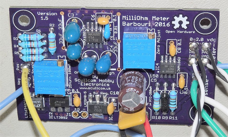
As indicated above, we use the Scullcom/Barbouri MilliOhmmeter (v1.5) board and we build our driver
board onto a small piece of good-quality perf board with through-plated holes on 0.1" pitch.
Below are some pix:
(click on any picture to see larger version)
Above, the Scullcom/Barbouri MilliOhmmeter Board, assembled.
Below, our driver board (top & bottom):

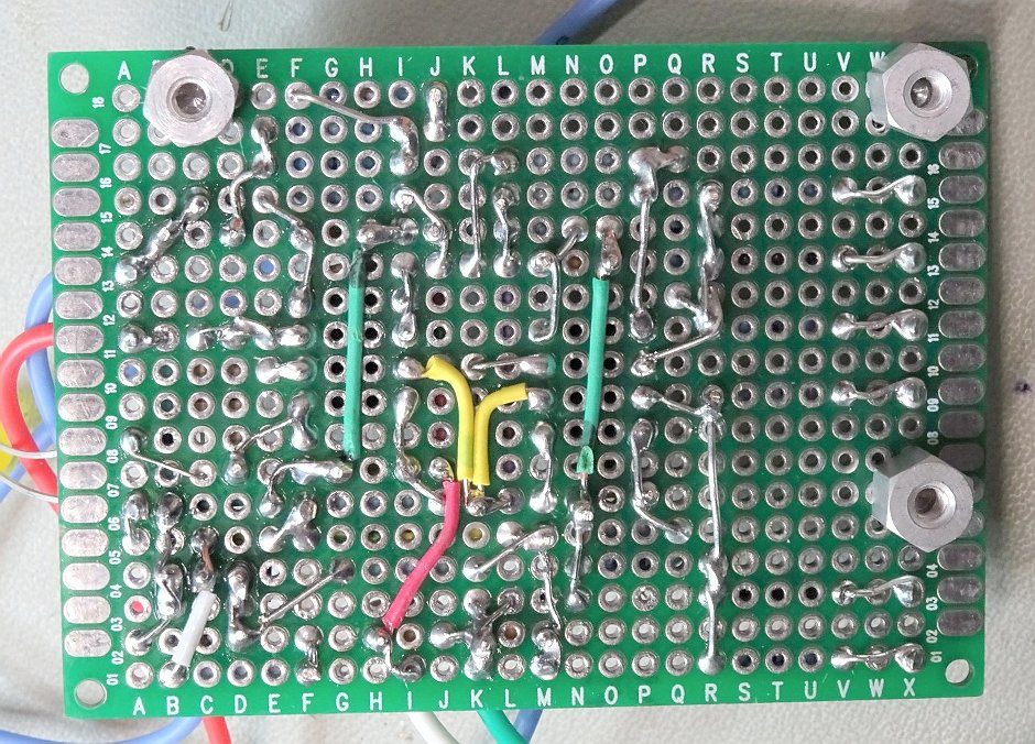
(click on any picture to see larger version)
Note: You can find the parts identification and layout on the enlarged schematic.
We thought a small aluminum enclosure with a sloped panel would work for this project. We selected
the 4"W x 6"L x 2.25"H LMB p/n MDC 642 would work nicely.
To fit these two boards inside the selected enclosure, they are stacked together, as shown below:
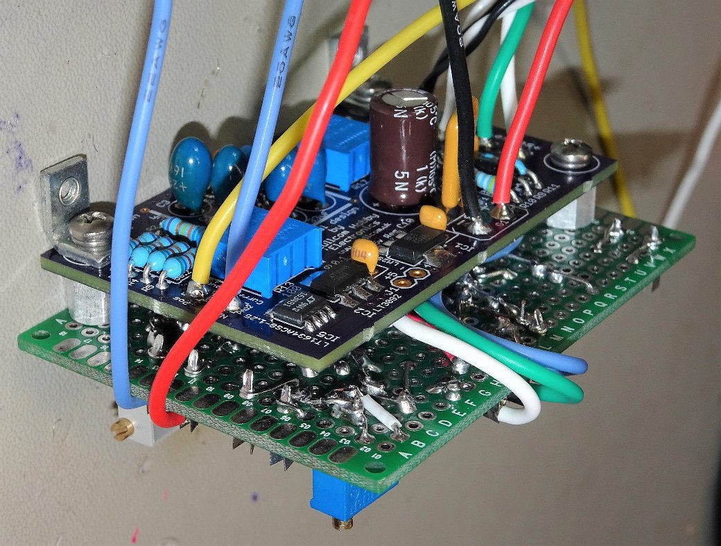
(click on any picture to see larger version)
Below is a view into the underside (intyerior) of our sloped-front enclosure:
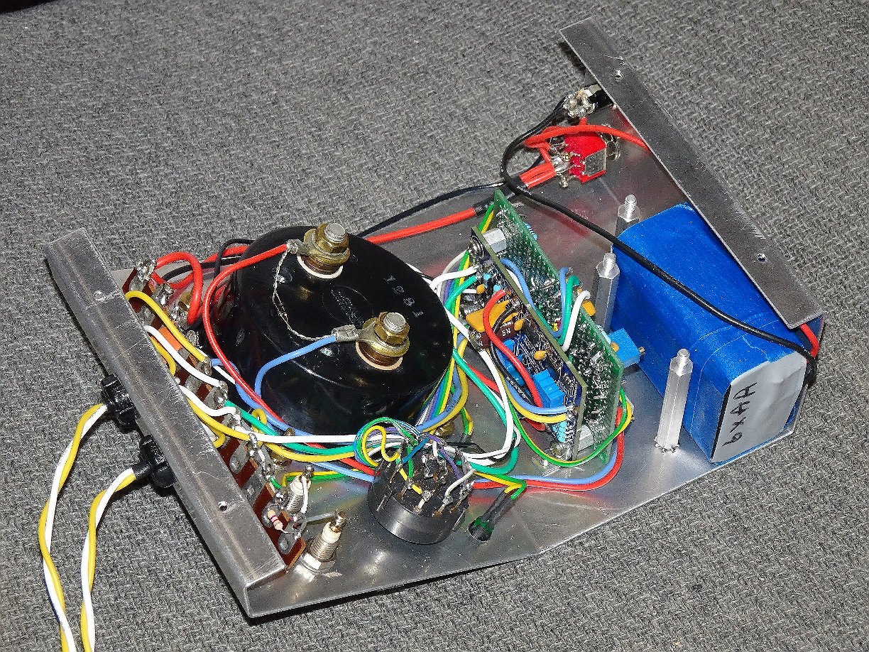
(click on any picture to see larger version)
A few things to notice above (left-to-right): TV-type terminal strips were used to solder and
anchor the probe leads (4-wires which form a kelvin probe). The big black round meter body, and
the 3-position switch which will be our range selection switch. Next, the stack of two boards,
described earler.And wrapped in blue, 6 X AA batteries, which comprise the internal 9V battery
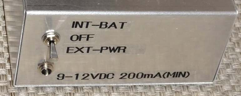
pack. Near that,on the back wall of the enclosure, is a DPDT-CO switch, which will be OFF when
in the center position,and select either the external 9-10V supply, or the internal battery pack.
See image below.
If running on internal battery, be aware that with sense leads open, current consumption is about
25 mA. During measurement, the constant current source will add another 100 mA (totaling 125 mA).
Batteries will not last long (4-6 Hours for a 9V 6xAA pack), so TURN OFF when not in actual use.
In this construction instance, each of two kelvin probes were formed using equal lengths (about
2 feet each) of AWG 20 wire, twisted together. At the probe end, they solder to a medium sewing
needle, with some heat shrink over the solder joint. For best accuracy, it is important to
construct the two probes identically.
At the milliOhmmeter board end, the two kelvin probes connect as follows:
   - Probe #1: One wire to Current Source 'Pos', Other wire to 'Sense +'
   - Probe #2: One wire to Current Source 'Neg', Other wire to 'Sense -'
Thus connected, the kelvin probe (needles) deliver the exact 100mA from the current source (to the
Calibrate the milliOhmmeter board first. This is done as follows, using your best (most accurate)
Digital Volt Meter (DVM). The calibration will only ever be LESS ACCURATE than the calibration
equipment you use. I use a DVM with +/-0.1% DC accuracy, and if I'm careful, I can probably
achieve calibration of +/-0.2%.
The milliOhmmeter board (Barbouri v1.5) has two trimpots. Monitor the meter output (+ meter -)
using your best DVM. Apply power. Let it warm up / stabilize for a minute or so. Short the Sense
Inputs (+ sense -) and adjust the "zero adjust" trimpot for best '0.0000'. Unshort the sense
inputs. Place your DVM in current measuring mode (usually, you have to also change one of the
probes), and place the DVM probes across the Current Source 'Pos' & 'Neg' so that current
flows. Adjust the "100mA adjust" to give a DVM reading of exactly 100.0 mA. Do this entire
procedure twice to assure you've got good calibration on the millliOhmmeter board before
proceeding to the N5ESE Analog Driver board.
Alternately, if you have your 4-wire kelvin probes already connected, and if you have a
high-precision resistor (0.1% or better) with a value in the range of 1-to-2-Ohm - let's say 1.5 Ohms -
you can place your kelvin probe (needles) firmly onto the resistor and adjust the "100mA adjust"
trimpot to give a measured (+ meter -) value of 1.5000V (in our example).
With the milliOhmmeter board calibrated, we can now calibrate our N5ESE Analog Driver board.
Turn the milliOhmmeter ON using the back panel switch. Let it warm up / stabilize for a minute
or so. Start on the 2.5 Ohm range, and short the probes together. It is best to use the needle tips
onto a small piece of copper board, as the sewing needles we used in our probes don't have the
best conductivity on their side edges. Ideally, with the probes open, the tellow LED should be
ON and the reading should be just past full scale. With the probes shorted, the reading should be
'0'. adjust the meter trimmer (mechanical trimmer on the analog meter itself) to give a best '0'
reading. Verify that all 3 ranges work in this way. Because of minute offsets in the difference
amplifier U1A, it may not be possible to get a perfect '0' on the lowest range while still having
a good '0' on the two upper ranges. (Or, it might...)
Initially, the analog meter full scale needs to be calibrated. I prefer to do this on the 2.5-Ohm
range. If you have a high-accuracy digital voltmeter (say+/-0.1% and at least 4 digits, you
can take any precision resistor (+/-1%) between 1-2 Ohms and attach the needle probes firmly.
Now measure the (+ meter -) on either board and note the reading (it should approximately match the
resistor). For example, using a 2.2-Ohm 1% reisitor, we might measure 2.1891 on our best DVM.
Now adjust the trimpot on the N5ESE Analog Driver board to make the meter deflection match as
closely as you can (with an anlog meter, it's a one-eyeball job). That's it! You're calibrated.
When using the analog milliOhmmeter, start at the highest range (2.5 Ohms, and work downwards,
finding the most suitable range for meter deflection that is as close to midrange as possible.
Doing it this way will atune your eye to the changes you are looking for (especially when looking
for a short on a PCB)
An open circuit causes the meter output of the main Milliohmmeter board to rise to about 4.9V.
To preclude damaging the analog meter, there is a clamp/clipper circuit that clips the meter drive
signal at 105% of Full Scale (i.e., about 2.63V). This will also illuminate a yellow LED indicating
"Over-Range".
By the way, I thought I would get cutesy and replace the sewing-needle probes with a commercial
probe that claims to be "woo-woo!". See the picture below - nice looking, huh? Alas - it made
for drifty readings when troubleshooting shorts. Likely the pressure-contact attachment point and
the probe-tip itself worked together to accomplish that. I would be better off to have the
soldered sewing needles. When it comes to low-ohm measurements, it's best to avoid any kind of
connector, and solder joints from tip (needle) all the way back to the milliOhmmeter Board is the best
solution.

I don't use this very often - a few times a year - but if I ever even think I might have a short-circuit,
this is the first tool I grab. And it has helped me many times identify an unwanted (and
sometimes invisible) solder bridge on a surface-mounted part.
73,
Monty N5ESE
dit dididit dit