(Click on any picture to get larger, high-resolution image)
Here's a nifty little weekend project you can build and package in any variety of ways. Sumner Eagerman WA1JOS (now SK), provides a neat little line of kits and assembled touch paddles and keyers, including the P3K kit, which we utilized in our build, shown here.
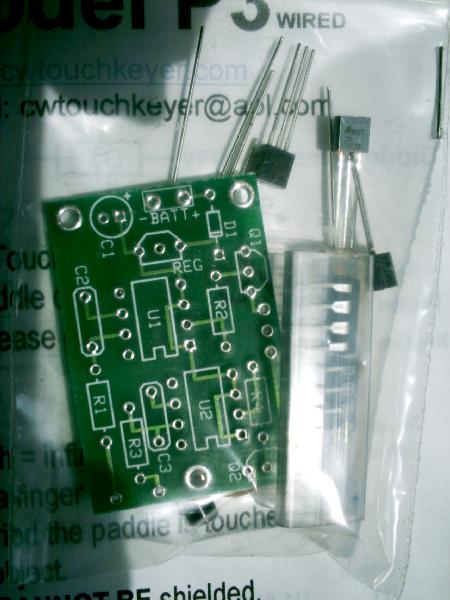
For less than $20, you get a nice pcb and two pre-programmed "touch key" chips, along with all the other electronic parts you'll need. The chips are the heart of the device, and Sumner has managed to do something well, where many have tried, but few have succeeded. I've tried a number of touch key paddles over the years, and I must say this is the only one I've felt really comfortable using. I'm not sure what his secret is (an adaptive algorithm for the detection, I'm guessing), but whatever it is, it WORKS!
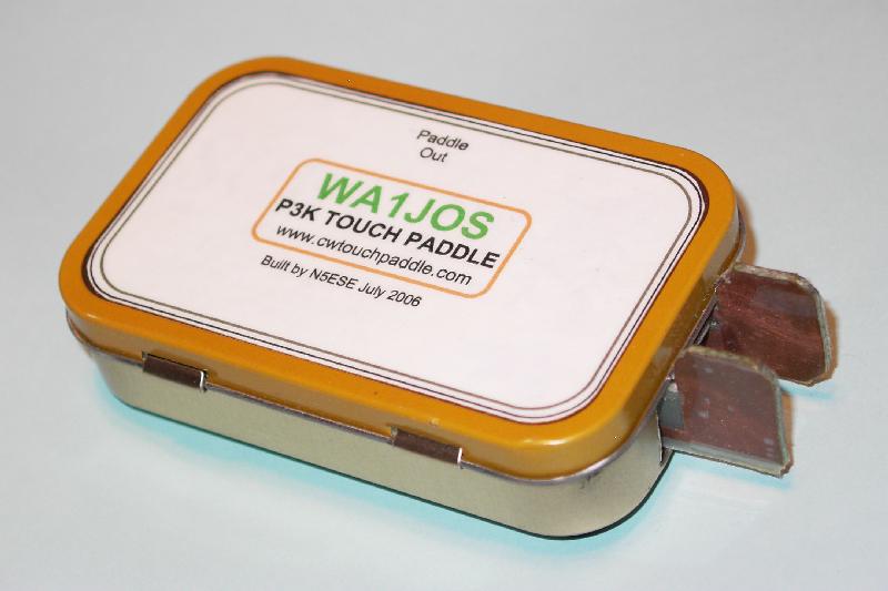
The other really neat aspect of this kit is that you are perfectly free to create your own paddle shape. The instructions make some suggestions, and that plants the seed for the imagination. Well, you know I had to put it in an Altoids tin. My goal was to have it completely self-contained so that I could stuff it in my field kit along with my ATS and T-1 Tuner, and have no fears that it might get broken, or get out of alignment. I think I've accomplished that.
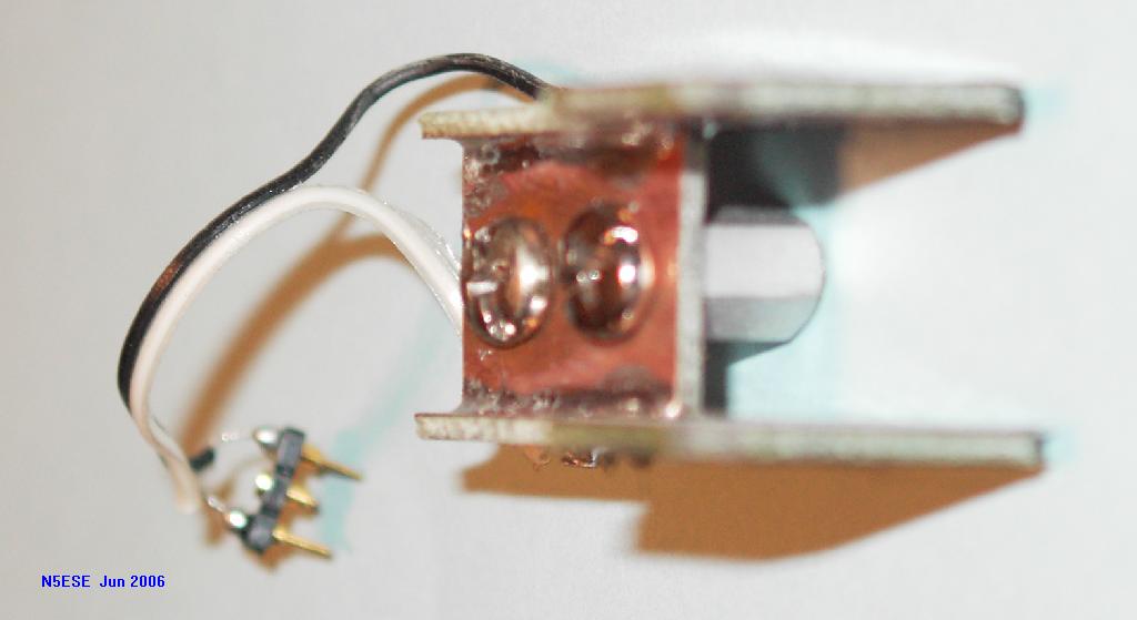
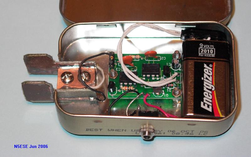
Board assembly is straightforward. Both a through-hole and SMD version are available now, but at the time I ordered mine, the SMD version was under development. Here's what mine looked like after assembly:
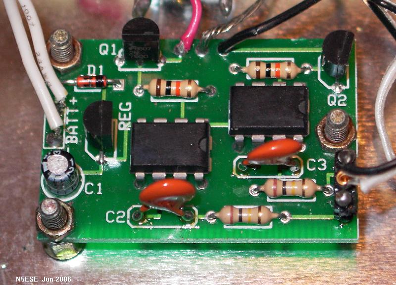
The wires on the left connect to the 9-Volt battery, the wires on the top connect to your transmitter (keyline), and the wires on the right connect to your homebrew capacitive paddle. Because I wanted to be able to "swap sides" (left and right paddle) if I needed to, I placed a 3-position pin header at the paddle pads on the pcb, and connect using a homebrew connector made from socket stock. In the pictures of the paddle which follow, you'll see the homebrew connector hanging on the cable coming from the homebrew paddle.
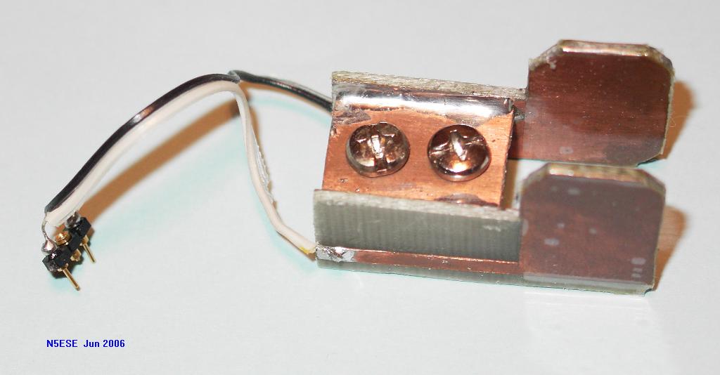
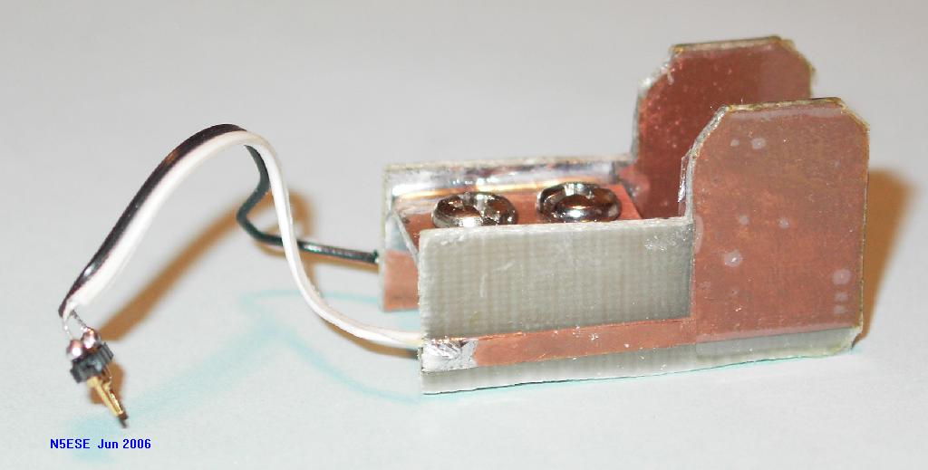
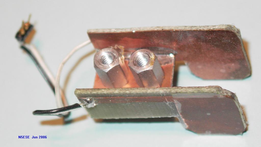
Now to the fun part - the paddle itself. The paddle needs to be capacitive, but not a lot of capacitance is required, and the paddles themselves can be insulated. I insulate mine with a few layers of clear packing tape, so the copper won't corrode from exposure to finger oils. My paddle is built from 3 pieces of scrap double-sided pc board stock, and two 3/8-inch long threaded spacers. Using a "nibbler", I shaped two identical paddles. Then, using the old tried-and-true "cut-and-peel" technique, I formed the copper islands and the trace that would connect each paddle to the input circuit connector. A third piece forms a bridge between the two paddles. We'll solder the three pieces together such that they form a single rigid assembly. Hey, no moving parts! The bridge will also serve to mount the two spacers,which in turn will hold the assembly securely to the altoid tin. A picture says a thousand words, so here's about 5000 words:
In order for the paddles to mount in the altoids tin, a little sheet metal work was required. I used - don't tell the XYL - a pair of kitchen shears to do the job:
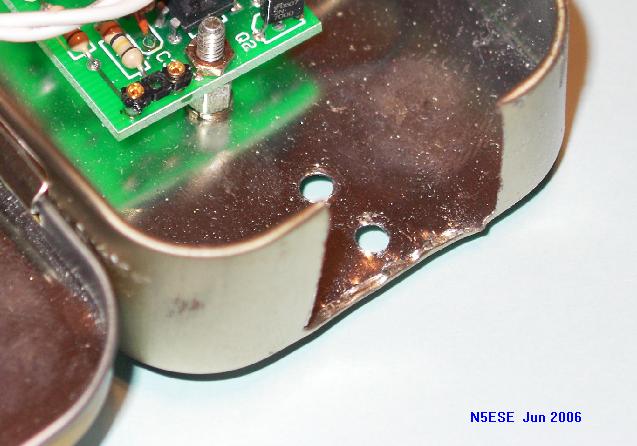
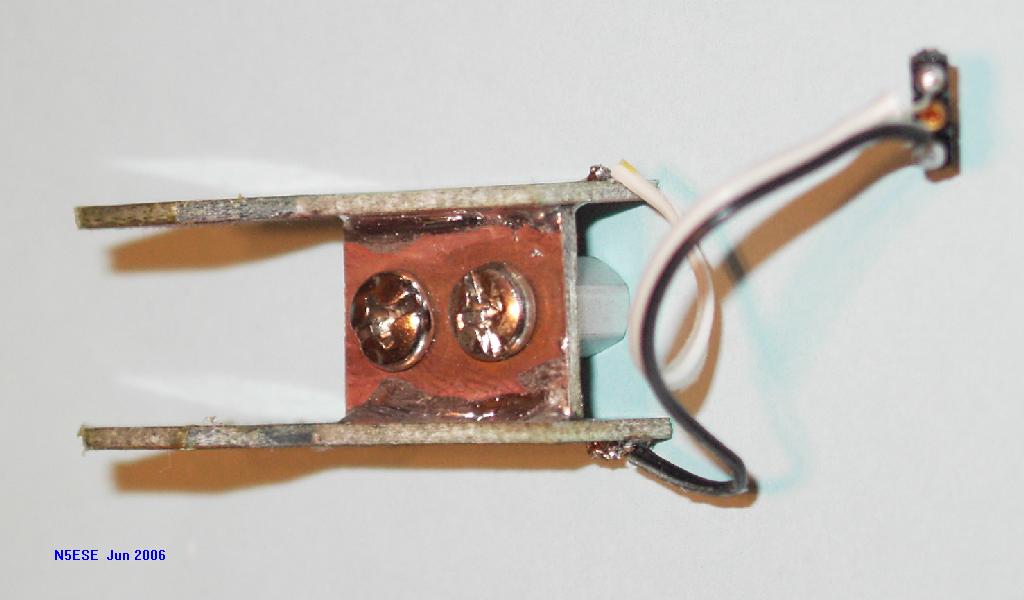
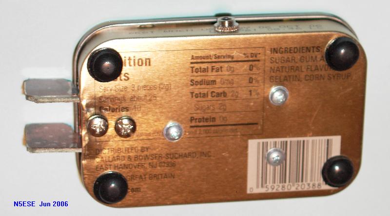
In the above picture, you can see the two holes where the paddle assembly will mount via its two spacers. The two screws which mount the paddle assembly (using the spacers) look like this from the bottom:
My original intention was that the paddle assembly itself could be dis-mounted and stored inside the altoids tin during transport. When so stowed, it looks like so:
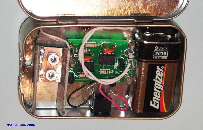
But I soon discovered it was so rugged, I really didn't need to stow it away, so most of the time it gets stuffed in the field kit with the paddles installed, which looks like so (with the cover open, or see picture at top of page for the "closed" look):
What about Performance?
As suggested by the instructions, to accommodate the non-standard paddle arrangement with its unique capacitances, I had to fool around with the values of the timing capacitors C2 & C3. At the standard values of 0.01uF, it was a tad under-sensitive, and I would occasionally miss a dit or dah, especially when trying to insert in iambic mode. For me, changing these to 0.02uF gave me perfect "feel". Installing this in the Altoids tin has an effect on the response, too. For example, if I put my opposite hand on the altoids tin, the device has a slightly more sensitive response. This is the way I actually optimized it, because I have a habit of "holding down" the paddle, no matter what paddle is. [It's embarrasing to be caught doing that with my 3-pound Begali paddle]. With or without the opposite hand, however, the circuitry has enough "adaptive response" to accommodate reliable keying. And that's impressive.
I highly recommend you acquire one of these paddle kits, create your own cool paddle (with your own unique twist), and put this baby in your portable kit. You'll be very glad you did!
73,
Monty N5ESE
dit dididit dit