N5ESE's Ballpoint RF Probe

(click on any picture to see larger version)
(click on any picture to see larger version)
| NOTE: 'N5FC' is my former call. This project was constructed while that call was valid, and you may observe references to it. |
This is one of those afternoon projects that can really be both rewarding to build and useful to have. Electrically, it's identical to the Classic RF Probe described elsewhere (where you can also find the theory discussion for this one). Like the Classic RF Probe, this one is used in conjunction with a high-impedance-input Voltmeter or Digital Voltmeter (DVM). See the schematic below. Cost? About $5, if you can scrounge the ballpoint pen, heat shrink, shielded cable, and copper tape.
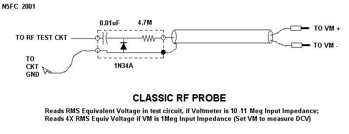
What makes this probe unique is that it's built inside the shell of a regular ol' ballpoint pen. Besides being conveniently compact, the unit sports a needle-probe suitable for use in probing surface-mount circuits, and good overall shielding. The pen cap protects the needle probe when not in use. When measuring sinusoidal signals, it should provide RMS-corrected readings, using a 10 or 11-Meg input impedance VTVM or DVM. With a 1-Meg DVM, it reads 25% of the sinusoidal RMS voltage. Reasonable accuracy (+/- 10%) can be expected over the HF/VHF range (2-150 MHz), although this hasn't been verified. When used to measure non-sinusoidal signals, the accuracy will be unknown, but it still affords good relative measurements, and most of the time, that's all that's required. It makes an excellent, compact, and portable accessory for troubleshooting or homebrewing QRP equipment with peak voltages less than 50 Volts (i.e., most solid-state equipment)
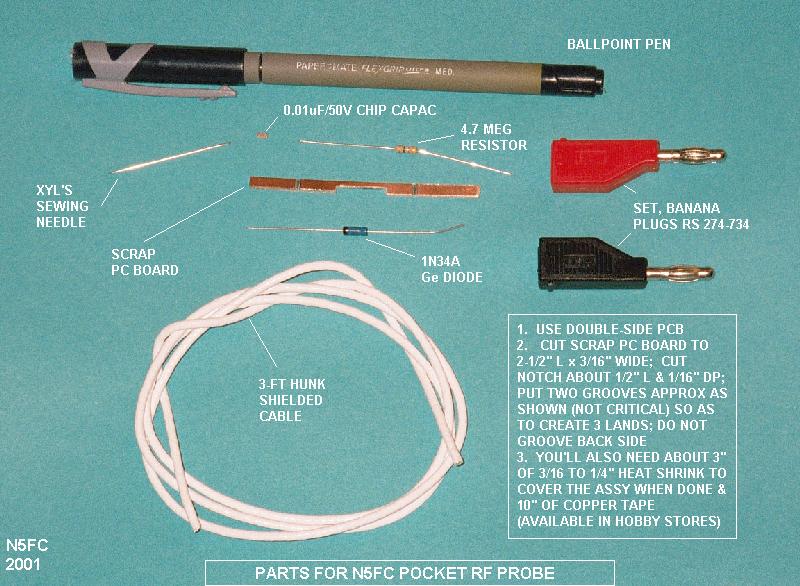
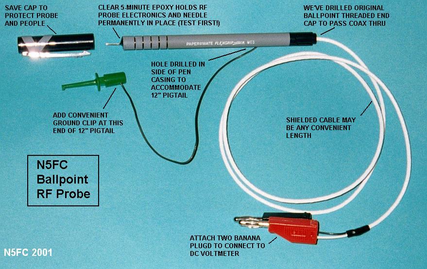
The figure below shows the parts required to build the Ballpoint RF Probe. Click on the image to open an larger, annotated image with parts labled, and construction notes. Pick a ballpoint pen with a non-metalized plastic body, and plenty of room inside. The Papermate Flexgrip model I used had an inside diameter a little over 1/4-inch. We'll use an itty-bitty scrap of double-sided printed-circuit-board to mount the electronic components. Trim the PC board to about 2-12" long and 3/16" wide; don't make it too wide, or it won't fit inside the ballpoint pen. Notch or file a little out of the middle of the pc board, so the 1N34A diode will fit easily inside the pen body. then, on one side only, groove in two places, so as to create 3 lands on the "top" side of the board. In addition to the parts shown, you'll need a 2-1/2" piece of heat-shrinkable tubing to cover the electronic assembly (although electrical tape would do instead), and about a foot of 1/4"-wide adhesive-backed copper tape, commonly available in rolls of 200-300 inches at large hobby stores (like Michaels, and Hobby Lobby). Although a chip capacitor is shown in the photo, a very small disc capacitor will do as well.
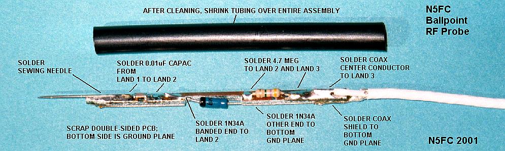
In the next image (below), we get a close-up of the electronics assembly. You can see the input capacitor straddling the front-to middle lands, and the 4.7 Meg resistor straddling the middle-to-rear lands. The diode, which snuggles into the notch, connects from the middle land to the ground plane on the rear side of the pc board. The diode's banded end goes to the middle land. Break the sewing needle in half, using two needle nose pliers. WARNING! Use eye and face protection!! ALSO NOTE: Don't try to cut a sewing needle with wire-cutters... you'll ruin the cutters. Avoid straight pins, which dont have the hardness to perform well as probes. Then, solder the sewing needle to the front land, centering it carefully. You might benefit from burnishing the solder-half of the sewing needle with some fine grit sandpaper, to make it take solder a little better. Center it up nicely, as that will make for a professional-looking probe. Solder the shielded cable to the top/bottom of the pc board, center conductor to the rear land on top, and shield to the ground plane on the bottom. Be careful to aviod straggling shield-wires which could short the electronics. Also,solder a 10-12" pigtail of good, flexible insulated wire onto the ground plane, pigtailed rearward. This will be used as the ground wire in our test circuit. Before you shrink the tubing over the electronic assembly, check for shorts between lands and from lands to ground plane, make sure you have the diode polarity correct, and check that the needle is making solid electrical contact, and is mechanically secure.
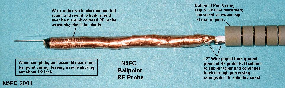
See the next image, below. After the electronic assembly has been heat-shrunk overall, wrap the copper tape all around the electronic assembly. This will be our shield. Near the rear of the electronic assembly, solder the electonic assembly's ground to the copper tape, near or on the cable shield. Alternative shielding methods can be tried, for example, you might pull the shield out of a piece of RG-59, and sleeve it over the electronic assembly, soldering it to the ground plane. Whatever you do, be certain that the shield cannot unravel and short against the probe itself or any of the electronics.
Although not shown in the picture, we drill a small hole about 2/3 back on the pen casing, threading the ground pigtail through the hole. This really tests your hand-to-eye coordination. If the pen has a threaded-in rear-cap, drill a hole in it just big enough to accommodate your main shielded cable. Thread the whole cable into the pen casing, and out the other side, and if you had a threaded rear-cap, like I did, thread it on. Pull the electronic assembly gently back into the casing, so that the needle probe sticks out about 1/2 inch. Mix some clear 5-minute epoxy, and let it thicken ever so slightly. Then , while holding the assembly vertically (i.e., probe-tip up), and using a small toothpick or screwdriver, drop epoxy into the probe area, sealing the electronics and probe into place. Allow to dry thoroughly before applying any pressure to the assembly.
When dry, attach your favorite ground-clip to the pigtail, and banana plugs on the end of the shielded cable (red to the center-conductor, black to the shield, to match your Voltmeter)
See the next image, below, which shows the completed assembly, annotated. Sometimes, seeing the entire assembly makes everything perfectly clear. Place the pen cap over the needle probe to protect the assembly when not in use.
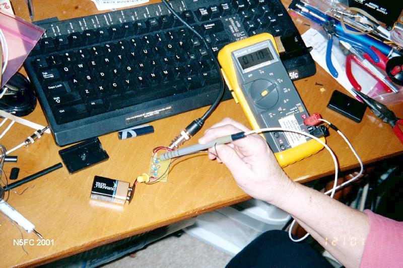
And speaking of use, here's our lovely model (OK...XYL) making a measurement in the N0SS Noise Generator. She has the ground clip connected to a convenient place in the circuit's ground, and the probe touches the test point we want to measure. As you can see, we read 0.710 Volts. Since this is broadband noise, the actual voltage reading is not accurate, but it was seen to be much greater than the previous stage, as we expected.
Let me know if you build one of these... and send me a picture!
73,
Monty N5ESE
dit dididit dit