TenTec 1315 / 1330 / 1340
Modifications for the TenTec QRP CW Transceiver Kit, with pictures

| NOTE: 'N5FC' is my former call. This project was constructed while that call was valid, and you may observe references to it. |
I have now built three of the tec Tec 13xx-series single-band QRP transceivers, and am more convinced than ever that (at $95) they are one of the best values in Amateur Radio. On this web page, I'll describe simple modifications I've done on these rigs, to overcome some common shortcomings. Not all kits need these mods, but many do. Some overcome minor inconveniences, and some potentially serious problems. If you have built one of these kits before, and encountered problems, I hope this page will help. If you have not built one, and would like more information about the rig in general, read my review of the Model 1340 -here-. And you can find the 13XX's specs at TenTec's amateur radio site -here-
This page describes my modifications for the three rigs I built, as follows:
NOTE: The first link is a MUST-READ, the second and third are MUST-DOs!
If you ever wanted to be confused about counting turns on toroid-wound inductors (such as encountered in this kit and many others), all you need to do is try to follow the "by-word" instructions in the TenTec manuals, then look at the drawings they provide. aaAARRGH! This can really mess with your mind. Here's my attempt to stir the water and make it clear as mud.
Pick up a toroid core in your left hand, and a piece of wire in your right. Stick one end of the wire straight through the center of the core, without bending it. This is turn "1". Now, bend it around the outside of the core, and again stick the end through the center of the core. That's "2" turns. Pull it tight, so the wire lays flat against the core all the way around, and the wire is sticking out in one direction, while starting from the exact opposite. If you count the wires laying against the inside of the core, you'll count "2". If you count the wires on the outside of the core, you'll count "1". This is a "2-turn" coil, and this is how TenTec wants you to count turns. So, if TenTec asks you to wind a toroid coil with 6 turns, you'll count 5 on the outside edge, and 6 "passes" on the inside. This is a common coil-winding convention, and you can see this illustrated below:
This mod is probably the most commonly required mod with this series of transceiver. Although the problem it cures is not encountered in all kits, and maybe not even most, it is still the most common problem encountered by builders of the TenTec 1300 series kit (as evidenced by the questions on maillists I have frequented over the years). In my case, I encountered the problem on all three of the kits I built (the 40, 30 and 15-Meter models), and this mod fixed them all. If you've not built your kit yet, I suggest you incorporate this modification as you build it, and avoid having to disassemble later.
The symptoms are as follows: When keying, the sidetone will be a loud hissy or buzzy sound, and the SWR (measured in the output circuit) will increase. The output power may go up or down, but I assure you, you don't want to transmit with this condition. At first I thought this was a low-frequency parasitic oscillation in the final amplifier, but lately I have been given to believe it is a near-frequency oscillation, rich in harmonics. The partially self-biased final may contribute to the susceptability of the final to oscillate (that mod later), but the root cause is printed-circuit board layout. The pc layout is pretty good all around, but it seems as if the TenTec designer ran out of board space as the final was being layed out, and serious compromises were made. The end result is that the three toroid-wound inductors in the final's low-pass filter and matching network (L8, L9, L10), can couple into each other and matching transformer T1, and the driver's L15. This makes the final amplifier prone to break into near-frequency oscillation when the output match is not perfectly resistive (and sometimes, even when it is). If you have an SWR meter in your output circuit, you'll see the SWR rise, and you wan't be able to make the SWR go to zero, because a significant part of the oscillation energy is at harmonics. Sometimes, if you pre-tune to provide a 50-ohm load, the final won't break into oscillation, until it warms up, or you move off-frequency. Either way, the sidetone will no longer sound sinusoidal (as it should in these tranceivers, which use a sample of the transmit signal, beat down to generate sidetone in the receiver).
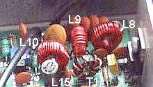
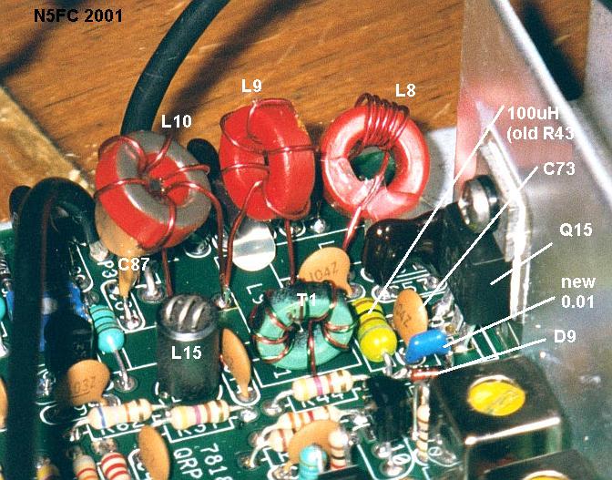
The fix is to relocate inductors L8, L9, and L10 to provide more separation and to keep them away from the final amp's matching transformer T1 and input components like L15. As built, the inductors are supposed to rest on or near the pcb, and come very close to touching each other and adjacent components. You can see this in the photo below, taken of the model 1340 before modification:
Here's a step-by-step for performing this mod:
- Pull the three core-wound inductors from the PI-Net output circuit (L8, L9, L10 in the models I worked on), and rewind them with leads about 3/8" longer (than they were previously). Strip the last 3/16" or so of the lead ends. When winding, count the number of times the wire passes the INSIDE of the core, or count the outside less one turn (for example, an 11-turn coil will show 10 wires on the outside, 11 passes on the inside (see section above). Arrange the turns as explained in the manual (spacing-wise), but ignore the pictorial when counting turns (some pictures are right, some are wrong)
- Reinstall the 3 inductors, leaving them suspended ABOVE the board.
- Arrange the coils so that they are at approximately 90 degree angles to adjacent coils, and away from the small balun transformer and all except output circuitry. Separate them by at least 1/4". Hold them in place temporarily with tape.
- Test to see if the PA is now stable with real loads < 2:1 SWR. Rearrange coils if necessary. Don't necessarily expect stability at "high" SWRs ( > 2:1, though it seems to "survive" them just fine).
- When satisfied, hot-glue the coils in place, using a single dab of hot glue under each coil and between the coil and whatever it sits on (could be the adjacent output capacitors).
Here are two pictures of the mod, as accomplished on a model 1315, and 1330 (left, right):
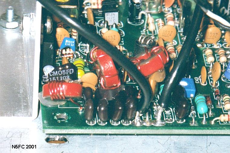
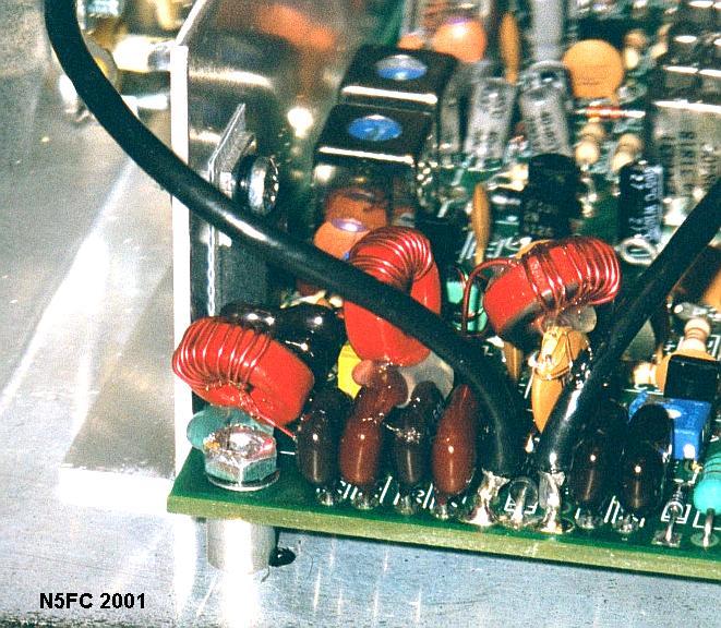
You may have noticed, while looking at the photos, some elements of other mods, most notably the silver-mica output capacitors, in place of disc capacitors; this mod is described below.
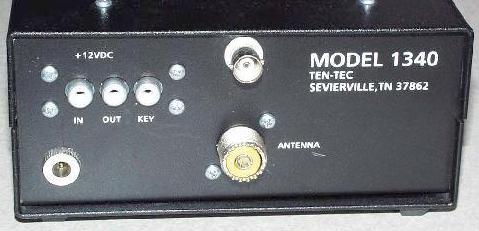
This is an absolute "must-do" if you value your work at all: DO NOT use the rear panel RCA Jacks for 12-Volt input power. I'd like to thrash the designer who thought it would be a good idea to put 12 volts on the center pin of an RCA plug, so that you could accidentally short it to ground more easily. Or, having successfully accomplished the power connection without smoking anything, accidently plug your key into 12 Volts and short it out or burn up your keyer (what were they thinking?).
Instead, drill a hole at the bottom left of the rear panel, centered about 3/4" from the left edge, and 1/2" up from the bottom. Here, install a barrel-type power jack, like the 5.5 x 2.1mm jack I got from Radio Shack (RS 274-1563). These are pretty foolproof. Be sure to get the corresponding mating plug, to connect to your battery or power supply (RS 274-1569 mates with my jack).
Here's a picture of the rear panel, showing the factory's RCA jacks, and my new power connector:
While operating the Model 1340 (for 40 Meters), which on my model outputs nearly 5 watts, I noticed a tendency to arc while I was adjusting the external Antenna Tuner (an MFJ-971). I tend to look askance at ceramic disk capacitors anyway, and suspected that one of them, located in the output low-pass-filter, might not be holding up to the task. The capacitors are sized for matched conditions, but marginally sized (voltage-wise) for mis-match conditions. I therefore opted to replace them with dipped silver-mica types, rated at 250V or better. I commonly get mine from Mouser Electronics, and they cost between 50 cents and a dollar each. I recommend the CD15 or smaller package.
I also noticed that the coupling capacitor for the T/R circuit (C87) was marginally rated for mismatch conditions, and decided to replace it with a ceramic disc rated for 1 KV, commonly used as RFI decoupling caps in AC-line circuits.
I consider these mods "optional". Here's what I did for each model:
Model 1315:
1. Remove C57, C58, C59, C98, C99, C88 (all 150 pF disc ceramics)
2. Replace with 150pF silver micas (p/n CD15FD151J03 / equiv)
3. Remove C87 (0.01 uF disc ceramic)
4. Replace with 0.01uF 1KV disc ceramic (Mouser p/n 539-GP110 / equiv)
Model 1330:
1. Remove C57, C88 (330 pF disc ceramics)
2. Replace with 330pF silver micas (p/n CD15FD331J03 / equiv)
3. Remove C58, C59 (680 pF disc ceramics)
4. Replace with 680pF silver micas (p/n CD15FC681J03 / equiv)
5. Remove C87 (0.01 uF disc ceramic)
6. Replace with 0.01uF 1KV disc ceramic (Mouser p/n 539-GP110 / equiv)
Model 1340:
1. Remove C57, C58, C59, C98, C99, C88 (all 470 pF disc ceramics)
2. Replace with 470 pF silver micas (p/n CD15FD471J03 / equiv)
3. Remove C87 (0.01 uF disc ceramic)
4. Replace with 0.01uF 1KV disc ceramic (Mouser p/n 539-GP110 / equiv)
You can see the 15 and 30 meter mods in the images above (along with the low-pass-filter inductors). Notice that sometimes I split the capacitors to accommodate what I had in my junk box. For example, on the 30-meter model, I used a 150 pF and 180 pF in parallel to sub for the 330 pF. There are extra positions on the PC board for doing this, which makes it convenient.
The stock TenTec 13xx series transceiver uses a modified fixed-bias circuit for its class AB final amplifier. A 2SC2166 is used for all bands except some of the higher bands use a 2SC1971. [Aside - the 2SC2166 requires an insulator, the 2SC1971 does not]. While trying to troubleshoot the final amplifier, I noticed that the bias circuit has no RF decoupling. This provides some self-bias, since the diode tends to rectify some of the incoming signal from the driver stage, and therefore provide more bias to the final stage. While this may seem like a hunky-dory idea, I think it helps to contribute to harmonics if the final amplifier is overdriven or breaks into oscillation. I therefore modified the bias circuit to provide true fixed bias. In so doing, I noticed that the output power has less tendency to drift up or down with keying, and seems quite stable all around. I have incorporated this mod into all three of my kits, but I consider this an "optional" mod. Here's what I did:
The original bias circuit looks like this:
Notice the lack of decoupling capacitors, and that a portion of the incoming RF (limited by R43) can reach the bias diode clamp, D9, to influence it. In our mod, remove R43 (usually, 100-ohms), and replace it with a small 100 uH choke (of the axial-leaded molded-epoxy variety; I used Digikey p/n M7837). Decouple the bias circuit across the diode, by tack-soldering a small 0.01 uF disc or monolithic capacitor across the diode D9 (you can use the capacitor C87 that you removed earlier from the output circuit mod). When you finish, the circuit will look like this, electrically and mechanically:
Click on the above image to see a larger version
The 13xx-series transceivers use the LM386 IC as the audio output amplifier. It is a common (and cheap) workhorse, but it is also well-known for having a significant and annoying "hiss" sound in the output. Fortunately, this is easily remedied (and I don't know why TenTec didn't incorporate this into the original circuit).
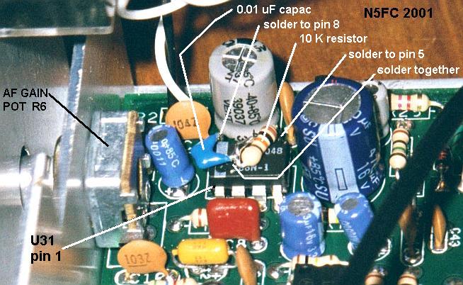
Add a small series-network, consisting of one 0.01 uF capacitor and one 10K resistor, between pins 5 and 8 of U1 (LM386). Keep all leads as short as possible, and keep the components away from other circuit components. I tack-soldered them directly to the IC pins, and arranged the components above the IC. See the image below:
A common complaint on the mail lists is loud popping in the sidetone as the rig is keyed. This doesn't translate to key clicks at the output, but if your model happens to have this "feature", it can be quite annoying. Of the three I build, only one had this problem, but I performed the mod on all three with no ill effects.
To perform this modification, remove electrolytic capacitor C1 (a 4.7 uF radial-leaded device located around mid-board) and replace it with a 0.1 uF disc or monolithic capacitor.
First, lets talk about VFO performance. The TenTec claim in their literature is that the VFO is "temperature-compensated". Hmmm... well, yes... sort of. It is true that they have used a polystyrene capacitor in one position in the tank circuit, presumably to offset a predicted drift that would occur due to warming of the FET junction, the inductor core, and the so-called "NPO" capacitors. However, the design does not accommodate part-to-part variation, and therefore it's almost guaranteed that the vfo will drift. (Usually, when someone talks about temperature compensation, they are talking about adjusting values of capacitors in conjunction with their thermal coefficients. to effect a zero or near-zero drift). The circuit is also electronically tuned via varactors, and subject to varactor drift and bias drift, neither of which can be disregarded. Nonetheless, the circuit performs OK, with drift that is acceptable for CW work, if you allow about 15-30 minutes warm-up, and don't subject the rig to large temperature excursions. In mine, the drift is typically less than 500 or 1000 Hz in the first ten or 15 minutes, and settles down to less than 100-200 Hz per hour.
If you encounter drift outside this range, try replacing the polystyrene capacitor first. If that does not fix it, replace the NPO capacitors, one at a time. I have occasionally encountered NPO capacitors that aren't anywhere near zero-temperature coefficient. Lastly, look at the inductor core and/or the JFET transistor.
When assembling the VFO, don't dope up the coil as suggested, using wax. This will melt the first time you take the unit out to the field. Here's what I do successfully: wind the coil as specified, but instead of mounting it on long leads, mount it onto the board, exactly where it is silkscreened. Test the range of it, according to the desired range, and as described in the manual. If it is too low in frequency, and can't be brought up by spreading turns, remove one turn from the coil. If it is too high in frequency, compress turns to lower it. Be careful - the VFO may work in the opposite direction to what the dial works, because of the mixing process. Make sure you understand what range you're VFO range really needs to be (it can be confusing). A frequency counter is EXTREMELY helpful in this regard. Borrow one if you don't own one.
After you get your coil wound and the range about right, glue it at the bottom of the coil, where the coil meets the board. Use a drop or two of quick-dry clear epoxy, or hot-glue. Then re-check the tuning range. In most cases, it will have changed somewhat. Spread turns (to raise the VFO frequency slightly) or squeeze turns together (to lower the frequency). You may have to tweak this later, in like manner, after the board is finished and assembled in the cabinet.
The first thing you'll no doubt notice is that the tuning rate is WAY too touchy. Depending on the model and your VFO settings, the tuning will cover 40 - 70 KHz in less than one turn. It can be extremely difficult to tune a signal to the correct audio frequency to provide "zero beat" on transmit with the received signal.
Some people have installed a 10-turn pot in place of the standard single-turn pot provided by TenTec, and some have added a vernier reduction dial to turn the standard pot. Both methods require some mechanical ingenuity, as the VFO tuning pot is mounted on a sub-panel about 1/4" behind the cabinet's front panel. To accommodate these methods, then, it's quite likely you'll have to cut the shaft on a pot. I hate doing that.
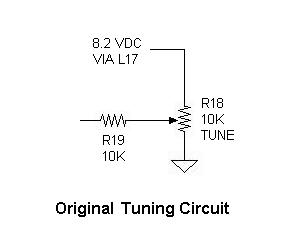
My solution is to add a new "Fine Tuning" control. We'll mount it near the tuning control, just to the right and slightly above the centerline of the main tuning control. It consists of a standard carbon pot, 500-ohms (Mouser 31CR205 or Digikey CT2201), and we'll wire it like a rheostat and place it in the power-side of the main tuning pot, R18. The "Fine Tuning" will provide a small amount of frequency dither, so that once we have the target signal "in our sights", we can use the fine tuning o match our sidetone signal's frequency (and thus "zero beat" the received signal"). After having used the 1340 for years without modification, I'm wondering why I hadn't done this mod years earlier. It's a dream, and simple to implement. Here's how we do it:
Temporarily remove the internal sub-panel that mounts the three pot controls. Mark-to-drill, a hole 1-1/4" to the right of the Main Tuning hole's vertical centerline, and 1/4" upward of the Main Tuning hole's horizontal centerline. Drill a hole to mount your 500-ohm Fine-tuning pot. (1/4" if you've used the pots I suggested, i.e., the Mouser 31CR205 or Digikey CT2201). Likewise, in the same relative location (relative to the Main Tuning hole centerlines), mark and drill a hole on the front panel. This hole can be bigger, to accommodate mismatch and tolerance stacking in the assembly. I drilled this as 3/8-inch. You'll also want to get a small knob to mount on your pot (I used Radio Shack 274-433, and painted the blue insert black).
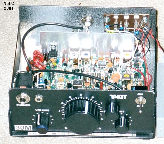
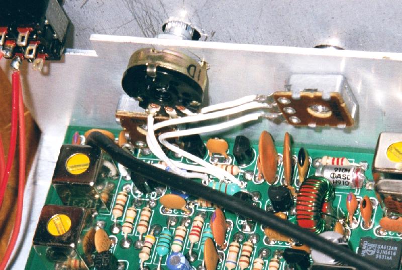
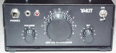
When done, the front panel looks like the image below, left. You can see the new "Fine Tuning" knob just below the "T" in "T-Kit" on the front panel. The image to the right shows the pot mounted on the internal sub-panel, viewed from behind the panel, and the mechanical arrangement of wiring.
Click on the above images to see a larger version
Electrically, wire the new Fine Tuning pot as shown in the diagrams below. You may have to experiment with which "end" of the Fine-Tuning pot to connect to the Main tuning pot, and which end to the 8.2 V side, to make the knob tune in the same apparent direction as the Main Tuning knob (i.e., turning clockwise to tune "up" in frequency).
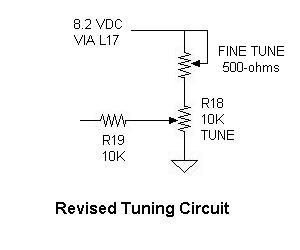
In practice, you set the Fine Tuning knob near its midpoint (non-critical), then tune in the desired station using the Main Tuning knob. Then tweak the Fine Tuning to get the received audio tone to approximately match your rig's transmit sidetone frequency (you'll quickly learn to know what this is). This brings you close to "zero beat".
The first model I built, the 1340 (40-meter version), had great selectivity, as can be seen in this spectrograph. The other two kits I built, did not. In fact, the selectivity was quite broad and the skirts were only moderate (on the 1330) to ill-defined (on the 1315). It was decided to replace all the crystals with crystals matched within 50 Hz. Fortunately, TenTec's design uses microprocessor-type crystals, which you can get at any number of national supply houses, for under a buck.
My 15-meter selectivity was the worst, so I started by ordering 25 each 16.000 MHz crystals, in the hopes of getting a set of 4 that would match to within 50 Hz. In fact, I got four sets of 4. I probably could have managed buying only 10 or 15 crystals, but I'll use the excess in a future homebrewing project, I'm sure. Matching was accomplished using my Altoids-packaged Crystal Checker in conjunction with the Az SQRPion Stinger Singer Audible Frequency Counter.
When I ordered my crystals, I ordered series-tuned crystals, not knowing what TenTec used, and later discovered that they used 20 pF loaded crystals. This is no big deal, but it required that I also change the transmit mixer oscillator crystal Y6 and BFO crystal Y5, because there is enough difference in frequency (about 2.5 KHz between the loading-types) that I could not tune to the proper "sideband". However, it is not necessary that Y5 and Y6 be matched to within 50 Hz of the filter crystals (100 or 200 Hz is close enough), so I could use some that were not part of a "matched set".
The result of matching the crystals was gratifying - a huge improvement - but still did not match the performance of the 11.00 MHz crystals in the 40-meter version. While I did not measure the performance of the 15-meter version, I'm guessing that the bandwidth is about 50% greater than the 40-meter version (meaning about 1.2 KHz vs the 40-meter's 700 Hz at the -6 dB points). I suspect the Q of the higher-frequency crystals is simply not high enough to effect really good filter performance, but it's still quite good for an "under $100" kit. And, I still get good single-signal selectivity and very good ultimate rejection.
I wanted to use my 13xx transceivers for short outings, back-packable. In receive, the kits draw a mere 30-35 mA, and a small set of batteries can easily power the receiver. I was willing to sacrifice the internal speaker, leaving plenty of room for batteries. I perused the market for good battery holders, and settled on some Eagle battery holders (Mouser 12BH334). Each holder, made of black thermoplastic, holds 3 AA cells, and comes pre-wired with 6" wire pigtails. Three fit neatly on the inside of the top cover, yielding 13.5V nominally. Here are some images of my battery installation:
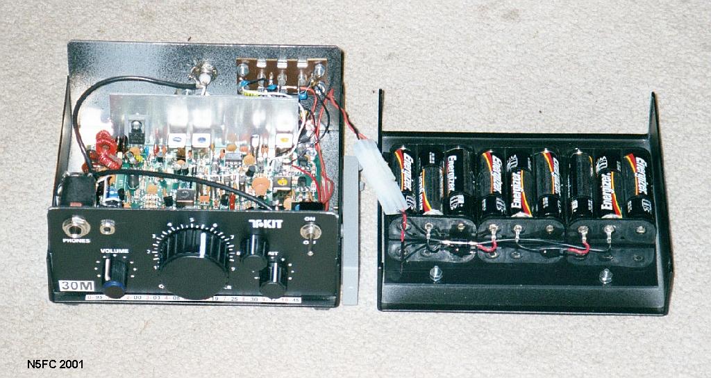
Take notice of a few things from the photos: The battery holders are mounted side-by-side using double-sided foam tape, onto a black plastic sheet just large enough to fit inside the top cover. The entire assembly, then, can be held on with the 4 screws/nuts that held on the speaker. In fact, because the battery assembly is also connectored (using an 2-conductor "ARES-style" set of Molex connectors, Radio Shack 274-222), I can remove the battery assembly and re-mount the speaker (if I wanted to).
You'll also notice a 1N5820 diode in series with the batteries. This diode serves to block DC voltage applied at the regular power jack, so that it won't attempt to charge my AA cells (which would be a no-no). A similar diode is placed at the regular input power jack, so the AA cells won't try to power the external power supply (which wastes the batteries). Use Schottky type rectifiers, rated at 3 Amps or more, to keep voltage drop to a minimum. Wired like this, whichever supply is higher in voltage supplies the transceiver circuitry (should both supplies be connected at once). Here's a schematic of the modification:
In practice, I could do about 2 hours of casual operating from a set of 9 AA alkaline batteries. At that point, battery voltage during transmit had dropped to about 10 volts, and I would only be getting about 2/3 power output (relative to full power at 13 Volts). For the 15-meter transceiver, which typically output about 3 watts at full voltage, this meant I had 2 watts at end-of-battery life (still, not bad). There was no chirp, nor other ill effects while using batteries, and the convenience factor of not having to carry a heavy gel-cell was a huge plus on outings.
On the 40-meter version, I installed a Small Wonders "Freq-Mite" Audible Frequency Annunciator, a swell gadget that generates a CW announcement of frequency whenever a button is pushed. It is capable of reading the VFO frequency and applying an offset and inverting if necessary to provide an audible "dial". Since the dial of the 13xx series tranceivers only has a logging scale, this can be very convenient.
I mounted my Freq-Mite on a small L-bracket attached to the internal front sub-panel. You can see the mechanical arrangement in the image below (along with other 1340 landmarks):
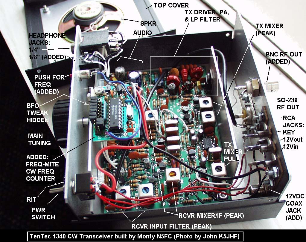
Electrically, the Freq-Mite requires a sample from the VFO, and I take that from C69 (at the output of the VFO's second buffer amp). The Freq-Mite generates an audio tone (in morse), and I inject that into the high side of AF Gain pot R6, through a 220K resistor. You may want to play with the resistor value, to balance the audio level of the frequency announcement (100K to 470K would be reasonable). Finally, I mounted a Radio-Shack pushbutton switch (normally open) near the top-left of the front panel, and wired it to the Freq-Mite. Pushing this switch tells the Freq-Mite to measure and send the VFO frequency, corrected for offset and inverted if necessary, to give the dial frequency.
Here's a picture of the front panel with the addition of the Freq-Mite's red pushbutton switch:
While I enjoyed the Freq-Mite on the 1340, I did not install it on the other versions, electing instead to use a dial-reading-to-frequency conversion table, attached to the radio.
When testing the 1330 (30--meter) version, I had some significant alignment problems in some stages. I don't know if the tank circuits were mis-designed or whether I just had some mis-marked coils, but I found I could not get a definitive "peak" when adjusting the front-end filter and transmit driver filters (which are nearly identical). This resulted in low sensitivity and low output power, until I made some changes to the tank circuits. Specifically, in the receiver front end:
Then, in the transmit driver filter:
- change C53 from 91 pF to 82 pF
- change C96 from 82 pF to 56 pF
After changing these capacitors, all stages peaked very nicely. I DID NOT need to similarly modify the 40 or 15-meter kits.
- change C60 from 82 pF to 62 pF
- change C61 from 91 pF to 82 pF
Unless I hear that others have encountered this same problem, I will not recommend doing this mod until you know you have the same problem. ...Back to the Mods Index...
Here's our catch-all section of miscellaneous mods.
- I opted to install a 1/8" jack (RS 274-248) at the rear panel, 7/8 " to the right of the new power jack, to plug my keyer into (since my keyer's output connector is a 1/8" mono plug).
- The 13xx series comes with a 1/4" stereo jack on the front panel, and I opted to wire a 1/8" stereo jack (RS 274-246) next to it (just to the right on the front panel). I could have, as easily, plugged an adapter (RS 274-367) into the 1/4" stereo jack to use my favorite lightweight 16-ohm earbuds. You can see this mod in the image above.
- The 13xx series uses the typical SO-239 UHF jack on the rear panel for your RF connection to the antenna. Since I prefer to use BNCs, I mounted a UG-1094 (RS 278-105) BNC Jack right above the factory jack. I could have, as easily, used an adapter, such as Radio Shack 278-121. You can see this mod in the image above.
- The factory-supplied speaker is hardwired to the main circuit assembly. This means that if you take the top off (for show-and-tell at your local QRP club meeting), the speaker and its wiring must accompany it around the room. Also, if you plan to add and remove internal batteries depending on whether you are portable or fixed, this arrangement doesn't work. I found some small rectangular connectors (of the variety used in personal computers for connecting speakers or batteries), and fabricated a mate out of 2-position square posts, and thus formed a way to remove the speaker entirely, via connector. Sorry, I don't have part numbers for those, but any small, 2-position connector set should do nicely.
- I've fallen in love with the Palm Radio Mini-Paddle, so it was only natural that I would attach the clip-on base to the lower right side of the 13xx case, so that I can snap the paddles on anytime I'm portable. By the way, if you haven't seen these paddles, they were originally designed for the Elecraft K2, but will easily adapt to any portable rig. One of the nifty features is that they retract completely inside the miniature extruded aluminum case, protecting them in transit. Also, they have the best feel of any portable paddle I've used. In fact, I sold my Bencher, and use these paddles full-time.
What other mods would I like?
The Transmit Mixer's Oscillator does not hold up well to transportation, especially when subjected to shipment via airline. Apparently, the adjustable coil (a shielded can type with a screw-type core) does not hold well when subject to vibration. Several times, after shipping, the transmit sidetone frequency is off by as much as 1 or 2 KHz. Since this is also the "match tone" for zero-beating the received signal, this can make it hard to zero beat the other station. I've been forced to pop the top and readjust the coil in the field, to get it back on frequency. It's a very touchy adjustment to begin with (which may be part of the cause), and I'd like a good mod to remedy that.
An internal keyer would be nice, so I wouldn't have to haul that around when back-packing. A Tick keyer or K1EL or KD1JV SKC keyer might do the trick nicely. There's lots of room inside for add-ins.
The outer case (as supplied by TenTec) is made of steel, and for serious backpackers (I'm not one of them), the extra weight can be objectionable. It would be quite easy to re-package this into an aluminum case about 3/4 of it's current volume, at considerable weight savings. I'm thinking about making a 2-band model by packaging 2 each 13xx assemblies into an old-style modem case. Or maybe a 4-band model into a slightly larger case.
The 13xx series transceivers have a nice AGC circuit in them, and one might easily tap and buffer that signal to provide drive for an S-meter.
Let me know of any additional mods you know of, and I'll reference them here.
73,
Monty N5ESE
dit dididit dit