N5ESE's Zero-Beat Tuning Aid
(click on any picture to see larger version)
(click on any picture to see larger version)
| NOTE: 'N5FC' is my former call. This project was constructed while that call was valid, and you may observe references to it. |
I never used to have problems hearing zero-beat when tuning my transceiver. But at some point, I turned into a geezer (Hey! not an OLD geezer!) and can't seem to find the right tone. You know the drill, typical on most transceivers. Preparing to answer a CQ on CW, and with the RIT off, you slowly tune the received signal until it reaches the magic tone that means "zero-beat". Usually, this is the same tone as your CW sidetone, 500-800 Hz, depending on your rig. You need a good ear for pitch.
Whether you're tone deaf, or just a geezer like myself, you might benefit with this handy little tuning aid. Connect it in parallel with your speaker or headphones. When you're ready to zero-beat the station calling CQ, press the pushbutton. This gives you about a minute to complete your tuning, at which time it shuts itself off, and conserves the 9 Volt battery. While it's on, tune through the signal slowly, stopping when the LED lights it's brightest. VOILA!, You're zero-beat! Backing down on the receiver's audio gain reduces the detection bandwidth, giving your zero-beat more accuracy, but I've found you can easily get within 100 Hz with normal volume levels.
(click on the picture to see larger version)
The circuit is a classic tone-detection application of the LM567 Tone Detector/PLL. Audio from the speaker or headphone line is applied to the LM567's input pin through coupling capacitor C3. Capacitors C1 and C2 set the PLL's bandwidth and loop filter characteristics. These values are non-critical and can be varied +/- 50% with no noticeable difference in performance. R3, in series with R2 and together with C4, sets the desired tone (i.e., the PLL reference), and should be set to the transceiver sidetone. Just key (into a dummy load), allowing sidetone audio to be applied to the LM567 input, and adjust R3 to provide the brightest illumination of LED1. With the resistor and pot values shown, you can set the detector to any tone between 300 and 2000 Hz.
S1, R5, C8 and Q1 form a time-delayed electronic switch for turning the circuit on and off, to conserve the 9 Volt battery. As shown, you can expect 6 months to a year of operation from an alkaline battery. Here's how it works: U2 is a micro-power 5 Volt regulator. It draws only 100uA when the circuit is in its "off" or "rest" state. In this state, no ground is applied to the LM567 and supporting circuitry. When S1 is pushed momentarily by the operator, C8, a 47 uF capacitor, is quickly charged up, and Q1's gate is simultaneously brought above it's "ON" threshold of roughly 2.5 Volts. When this happens, Q1 turns "on", providing a low resistance path from its Drain to its Source, and so a ground for the LM567 and supporting circuitry now exists. As the pushbutton is released, C8 begins to discharge through 1 M resistor R5, but it takes about 45-60 seconds before Q1's Gate voltage falls below the "ON" threshold, which will once again turn the circuit off. This gives the operator (and the LM567 PLL) plenty of time to do the tuning job, but allows the 9 Volt battery to be conserved, because it only supplies significant current when required.
If you don't want the added complexity of the automatic power switch, replace it entirely with a conventional SPST switch. Keep the regulator though, so that the PLL circuit's reference frequency will not be affected by voltage variations as the 9V battery dies. If you don't use the automatic power circuitry, an 78L05 will work for the regulator.
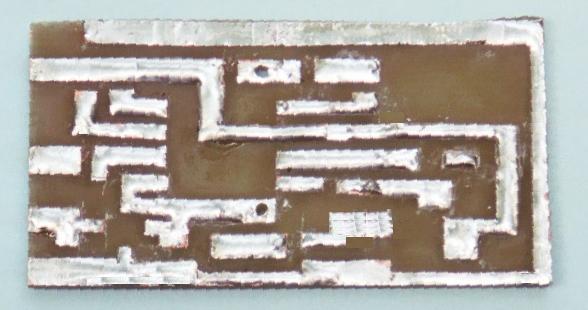
I constructed mine on a small PC board, using a hobby knife and "cut and peel" techniques to "etch" the PC pattern.
I sized the board to just fit inside the border of a plastic 9-Volt battery holder. All parts were surface mounted, even the "thru-hole" parts (like attached wires, pot, regulator, and the DIP IC). Where possible, surface mount caps and resistors were used. When assembled, the board was mounted on the back of the battery holder, providing an extremely light and compact assembly. Here's what it looks like:
And here's the layout, annotated:
(click on the picture to see larger version)
You can find a photo of the raw PCB -here-
The circuit will work as well with other construction techniques and regular thru-hole components, so feel
free to use your own favorite construction techniques and whatever parts you have in your junk box.
73,
Monty N5ESE
dit dididit dit